GA-F2A55M-DS2 User's Manual Rev.
Motherboard GA-F2A55M-DS2 Aug. 20, 2012 GA-F2A55M-DS2 Motherboard Aug.
Copyright ©©2012 GIGA-BYTE TECHNOLOGY CO., LTD. All rights reserved. The trademarks mentioned in this manual are legally registered to their respective owners. Disclaimer Information in this manual is protected by copyright laws and is the property of GIGABYTE. Changes to the specifications and features in this manual may be made by GIGABYTE without prior notice.
Table of Contents GA-F2A55M-DS2 Motherboard Layout............................................................................5 GA-F2A55M-DS2 Motherboard Block Diagram................................................................6 Chapter 1 Hardware Installation......................................................................................7 1-1 1-2 1-3 1-4 1-5 1-6 1-7 1-8 Installation Precautions.....................................................................................
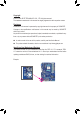
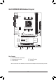
KB_MS DDR3_1 DDR3_2 GA-F2A55M-DS2 Motherboard Layout ATX_12V VGA Socket FM2 ATX DVI CPU_FAN R_USB SATA2 2 3 USB_LAN AUDIO Realtek GbE LAN BAT GA-F2A55M-DS2 iTE Super I/O PCIEX16 PCIEX1 M_BIOS AMD A55 B_BIOS PCI CODEC CLR_CMOS COM F_AUDIO SYS_FAN SPDIF_O SATA2 0 1 F_USB1 F_USB2 F_PANEL Box Contents 55 GA-F2A55M-DS2 motherboard 55 Motherboard driver disk 55 User's Manual 55 Two SATA cables 55 I/O Shield * The box contents above are for reference only and the actual items shall dep
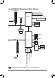
GA-F2A55M-DS2 Motherboard Block Diagram 1 PCI Express x16 APU CLK+/- (100 MHz) DISP CLK+/- (100 MHz) 1 PCI Express x1 DDR3 1866/1600/1333/1066 MHz AMD APU Dual Channel Memory PCIe CLK (100 MHz) x16 PCI Express Bus DVI-D x1 D-Sub x1 UMI Realtek GbE LAN RJ45 LAN PCI Bus 8 USB 2.0/1.
Chapter 1 Hardware Installation 1-1 Installation Precautions The motherboard contains numerous delicate electronic circuits and components which can become damaged as a result of electrostatic discharge (ESD). Prior to installation, carefully read the user's manual and follow these procedures: •• Prior to installation, make sure the chassis is suitable for the motherboard. •• Prior to installation, do not remove or break motherboard S/N (Serial Number) sticker or warranty sticker provided by your dealer.
1-2 Product Specifications APU FM2 Socket: - AMD A series processors - AMD Athlon™ series processors (Go to GIGABYTE's website for the latest APU support list.) Chipset AMD A55 Memory 2 x 1.
Internal Connectors Back Panel Connectors 1 x 24-pin ATX main power connector 1 x 8-pin ATX 12V power connector 4 x SATA 3Gb/s connectors 1 x APU fan header 1 x system fan header 1 x front panel header 1 x front panel audio header 1 x S/PDIF Out header 2 x USB 2.0/1.1 headers 1 x serial port header 1 x Clear CMOS jumper 1 x PS/2 keyboard port 1 x PS/2 mouse port 1 x D-Sub port 1 x DVI-D port 4 x USB 2.0/1.
Bundled Software Operating System Form Factor Norton Internet Security (OEM version) Support for Microsoft® Windows 8/7/Vista/XP Micro ATX Form Factor; 22.5cm x 17.4cm * GIGABYTE reserves the right to make any changes to the product specifications and product-related information without prior notice. * Please visit GIGABYTE's website to check the supported operating system(s) for the software listed in the "Unique Features" and "Bundled Software" columns.
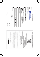
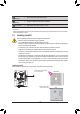
1-4 Installing the Memory Read the following guidelines before you begin to install the memory: •• Make sure that the motherboard supports the memory. It is recommended that memory of the same capacity, brand, speed, and chips be used. (Go to GIGABYTE's website for the latest supported memory speeds and memory modules.) •• Always turn off the computer and unplug the power cord from the power outlet before installing the memory to prevent hardware damage. •• Memory modules have a foolproof design.
1-6 Setup of the AMD Dual Graphics Configuration Combining the onboard GPU with a discrete graphics card, AMD's Dual Graphics technology can provide significantly advanced display performance for AMD platform. Read the following instructions on configuring a Dual Graphics system. A.
1-7 Back Panel Connectors PS/2 Keyboard and PS/2 Mouse Port Use the upper port (green) to connect a PS/2 mouse and the lower port (purple) to connect a PS/2 keyboard. D-Sub Port The D-Sub port supports a 15-pin D-Sub connector. Connect a monitor that supports D-Sub connection to this port. DVI-D Port (Note) The DVI-D port conforms to the DVI-D specification and supports a maximum resolution of 2560x1600. Connect a monitor that supports DVI-D connection to this port.
1-8 Internal Connectors 1 2 3 5 12 8 5 7 4 10 9 6 11 1) ATX_12V 7) F_AUDIO 2) ATX 8) SPDIF_O 3) CPU_FAN 9) F_USB1/F_USB2 4) SYS_FAN 10) COM 5) SATA2 0/1/2/3 11) CLR_CMOS 6) F_PANEL 12) BAT Read the following guidelines before connecting external devices: •• First make sure your devices are compliant with the connectors you wish to connect. •• Before installing the devices, be sure to turn off the devices and your computer.
1/2) ATX_12V/ATX (2x4 12V Power Connector and 2x12 Main Power Connector) With the use of the power connector, the power supply can supply enough stable power to all the components on the motherboard. Before connecting the power connector, first make sure the power supply is turned off and all devices are properly installed. The power connector possesses a foolproof design. Connect the power supply cable to the power connector in the correct orientation.
3/4) CPU_FAN/SYS_FAN (Fan Headers) All fan headers on this motherboard are 4-pin. Most fan headers possess a foolproof insertion design. When connecting a fan cable, be sure to connect it in the correct orientation (the black connector wire is the ground wire). The motherboard supports APU fan speed control, which requires the use of a APU fan with fan speed control design. For optimum heat dissipation, it is recommended that a system fan be installed inside the chassis. 1 Pin No.
6) F_PANEL (Front Panel Header) Connect the power switch, reset switch, speaker, and system status indicator on the chassis to this header according to the pin assignments below. Note the positive and negative pins before connecting the cables. Power Switch Hard Drive Reset Activity LED Switch F_PANEL (H61M-D2) Power LED Chassis Intrusion Header •• MSG/PWR (Message/Power/Sleep LED): Connects to the power status indicator on the chassis front panel.
7) F_AUDIO (Front Panel Audio Header) The front panel audio header supports Intel High Definition audio (HD) and AC'97 audio. You may connect your chassis front panel audio module to this header. Make sure the wire assignments of the module connector match the pin assignments of the motherboard header. Incorrect connection between the module connector and the motherboard header will make the device unable to work or even damage it. 9 10 1 2 For HD Front Panel Audio: Pin No.
9) F_USB1/F_USB2 (USB 2.0/1.1 Headers) The headers conform to USB 2.0/1.1 specification. Each USB header can provide two USB ports via an optional USB bracket. For purchasing the optional USB bracket, please contact the local dealer. 9 10 1 2 Pin No. 1 2 3 4 5 6 7 8 9 10 Definition Power (5V) Power (5V) USB DXUSB DYUSB DX+ USB DY+ GND GND No Pin NC •• Do not plug the IEEE 1394 bracket (2x5-pin) cable into the USB header.
11) CLR_CMOS (Clear CMOS Jumper) Use this jumper to clear the CMOS values (e.g. date information and BIOS configurations) and reset the CMOS values to factory defaults. To clear the CMOS values, use a metal object like a screwdriver to touch the two pins for a few seconds. Open: Normal Short: Clear CMOS Values •• Always turn off your computer and unplug the power cord from the power outlet before clearing the CMOS values.
Chapter 2 BIOS Setup BIOS (Basic Input and Output System) records hardware parameters of the system in the CMOS on the motherboard. Its major functions include conducting the Power-On Self-Test (POST) during system startup, saving system parameters and loading operating system, etc. BIOS includes a BIOS Setup program that allows the user to modify basic system configuration settings or to activate certain system features.
2-1 Startup Screen The following startup Logo screen will appear when the computer boots. Function Keys Function Keys: : BIOS SETUP\Q-FLASH Press the key to enter BIOS Setup or to access the Q-Flash utility in BIOS Setup. : SYSTEM INFORMATION Press the key to display your system information. : BOOT MENU Boot Menu allows you to set the first boot device without entering BIOS Setup.
2-2 The Main Menu A. The 3D BIOS Screen (Default) On GIGABYTE's uniquely designed 3D BIOS screen, you can use your mouse to move through the motherboard image and click to enter the function menu in each area for quick configuration. For example, pass your mouse arrow over the CPU and memory sockets and enter the System Tuning menu to configure CPU/memory frequency, memory timings, and voltage settings.
BIOS Setup Program Function Keys <+>/ <->/ Move the selection bar to select a setup menu Move the selection bar to select an configuration item on a menu Execute command or enter a menu Increase the numeric value or make changes Decrease the numeric value or make changes Switch to 3D BIOS screen Restore the previous BIOS settings for the current submenus Load the Optimized BIOS default settings for the current submenus Acc
2-3 M.I.T. Whether the system will work stably with the overclock/overvoltage settings you made is dependent on your overall system configurations. Incorrectly doing overclock/overvoltage may result in damage to CPU, chipset, or memory and reduce the useful life of these components. This page is for advanced users only and we recommend you not to alter the default settings to prevent system instability or other unexpected results. (Inadequately altering the settings may result in system's failure to boot.
`` M.I.T. Current Status This screen provides information on CPU/memory frequencies/parameters. `` Advanced Frequency Settings && BCLK/PCIe Clock Control Allows you to manually set the CPU base clock and PCIe bus frequency in 1 MHz increments. (Default: Auto) Important: It is highly recommended that the CPU frequency be set in accordance with the CPU specifications. && Processor Graphics Clock Allows you to set the onboard graphics clock. The adjustable range is from 300 MHz to 2000 MHz.
`` Advanced CPU Core Features && CPU Clock Ratio, CPU Frequency The settings above are synchronous to those under the same items on the Advanced Frequency Settings menu. && Core Performance Boost (Note) Allows you to determine whether to enable the Core Performance Boost (CPB) technology, a CPU performance-boost technology. (Default: Enabled) (Default: Auto) && CPB Ratio (Note) Allows you alter the ratio for the CPB. The adjustable range is dependent on the CPU being installed.
&& AMD Memory Profile (A.M.P.) (Note) Allows the BIOS to read the SPD data on AMP memory module(s) to enhance memory performance when enabled. Disabled Disables this function. (Default) Profile1 Uses Profile 1 settings. (Note) Profile2 Uses Profile 2 settings. && System Memory Multiplier Allows you to set the system memory multiplier. Auto sets memory multiplier according to memory SPD data.
&& Profile VTT Voltage The value displayed here is dependent on the CPU being used. && Rank Interleaving Enables or disables memory rank interleaving. Enabled allows the system to simultaneously access different ranks of the memory to increase memory performance and stability. (Default: Enabled) && Channel Interleaving Enables or disables memory channel interleaving. Enabled allows the system to simultaneously access different channels of the memory to increase memory performance and stability.
`` Advanced Voltage Settings This sub-menu allows you to set CPU, Chipset, and memory voltages. `` PC Health Status && Reset Case Open Status Disabled Keeps or clears the record of previous chassis intrusion status. (Default) Enabled Clears the record of previous chassis intrusion status and the Case Open field will show "No" at next boot.
&& Case Open Displays the detection status of the chassis intrusion detection device attached to the motherboard CI header. If the system chassis cover is removed, this field will show "Yes", otherwise it will show "No". To clear the chassis intrusion status record, set Reset Case Open Status to Enabled, save the settings to the CMOS, and then restart your system. && CPU Vcore/Dram Voltage/+3.3V/+5V/+12V Displays the current system voltages.
2-4 System This section provides information on your CPU, memory, motherboard model, and BIOS version. You can also select the default language used by the BIOS and manually set the system time. && System Language Selects the default language used by the BIOS. && System Date Sets the system date. The date format is week (read-only), month, date, and year. Use to switch between the Month, Date, and Year fields and use the or key to set the desired value.
2-5 BIOS Features && Boot Option Priorities Specifies the overall boot order from the available devices. For example, you can set hard drive as the first priority (Boot Option #1) and DVD ROM drive as the second priority (Boot Option #2). The list only displays the device with the highest priority for a specific type. For example, only hard drive defined as the first priority on the Hard Drive BBS Priorities submenu will be presented here.
&& Full Screen LOGO Show Allows you to determine whether to display the GIGABYTE Logo at system startup. Disabled skips the GIGABYTE Logo when the system starts up. (Default: Enabled) && CSM Support Enables or disables UEFI CSM (Compatibility Support Module) to support a legacy PC boot process. Always Enables UEFI CSM. (Default) Never Disables UEFI CSM and supports UEFI BIOS boot process only. && Boot Mode Selection Allows you to select which type of operating system to boot.
&& Ipv6 PXE Support Enables or disables IPv6 PXE Support. This item is configurable only when Network stack is enabled. && Administrator Password Allows you to configure an administrator password. Press on this item, type the password, and then press . You will be requested to confirm the password. Type the password again and press . You must enter the administrator password (or user password) at system startup and when entering BIOS Setup.
&& Enable all USB device Enables or disables the integrated USB 2.0/1.1 controller. (Default: Enabled) && HD Audio Azalia Device Enables or disables the onboard audio function. (Default: Enabled) If you wish to install a 3rd party add-in audio card instead of using the onboard audio, set this item to Disabled. && IOMMU Enables or disables AMD IOMMU support. (Default: Enabled) && Onboard LAN Controller Enables or disables the onboard LAN function.
&& PORT0 Hot Plug~PORT3 Hot Plug Enables or disable the hot plug capability for each SATA port. (Default: Disabled) && SATA Power on PORT0~SATA Power on PORT3 Enables or disables each SATA port. (Default: Enabled) `` GFX Configuration && Primary Video Device Specifies the first initiation of the monitor display from the installed PCI Express graphics card or the onboard graphics. IGD Video Sets the onboard graphics as the first display.
2-7 Power Management && Resume by Alarm Determines whether to power on the system at a desired time. (Default: Disabled) If enabled, set the date and time as following: Wake up day: Turn on the system at a specific time on each day or on a specific day in a month. Wake up hour/minute/second: Set the time at which the system will be powered on automatically.
&& Power On By Keyboard Allows the system to be turned on by a PS/2 keyboard wake-up event. Note: To use this function, you need an ATX power supply providing at least 1A on the +5VSB lead. Disabled Disables this function. (Default) Password Set a password with 1~5 characters to turn on the system. Keyboard 98 Press POWER button on the Windows 98 keyboard to turn on the system. Any Key Press any key to turn on the system.
2-8 Save & Exit && Save & Exit Setup Press on this item and select Yes. This saves the changes to the CMOS and exits the BIOS Setup program. Select No or press to return to the BIOS Setup Main Menu. && Exit Without Saving Press on this item and select Yes. This exits the BIOS Setup without saving the changes made in BIOS Setup to the CMOS. Select No or press to return to the BIOS Setup Main Menu.
Chapter 3 Drivers Installation •• Before installing the drivers, first install the operating system. •• After installing the operating system, insert the motherboard driver disk into your optical drive. The driver Autorun screen is automatically displayed which looks like that shown in the screen shot below. (If the driver Autorun screen does not appear automatically, go to My Computer, double-click the optical drive and execute the Run.exe program.
B. Configuring SATA controller mode in BIOS Setup Make sure to configure the SATA controller mode correctly in system BIOS Setup. For the BIOS Setup menus, refer to Chapter 2, "BIOS Setup," "Integrated Peripherals." Steps: 1. Turn on your computer and press to enter BIOS Setup during the POST (Power-On Self-Test). Ensure OnChip SATA Channel is enabled under Peripherals. To enable RAID for the SATA2 0/1/2/3 connectors, set OnChip SATA Type to RAID. 2. Save changes and exit BIOS Setup.
8. After the creation is complete, the screen will return to LD View Menu where you will see the newlycreated array. 9. Press to return to Main Menu and press again if you want to exit the RAID BIOS utility. Making a SATA RAID/AHCI Driver Diskette Before installing Windows XP, connect a USB floppy disk drive to your computer first because you need to install the SATA RAID/AHCI driver from a floppy disk that contains the driver during the OS installation.
Regulatory Statements Regulatory Notices This document must not be copied without our written permission, and the contents there of must not be imparted to a third party nor be used for any unauthorized purpose. Contravention will be prosecuted. We believe that the information contained herein was accurate in all respects at the time of printing. GIGABYTE cannot, however, assume any responsibility for errors or omissions in this text.
- 45 -
- 46 -
- 47 -
Contact Us GIGA-BYTE TECHNOLOGY CO., LTD. Address: No.6, Bao Chiang Road, Hsin-Tien Dist., New Taipei City 231, Taiwan TEL: +886-2-8912-4000, FAX: +886-2-8912-4003 Tech. and Non-Tech. Support (Sales/Marketing) : http://ggts.gigabyte.com.tw WEB address (English): http://www.gigabyte.com WEB address (Chinese): http://www.gigabyte.tw You may go to the GIGABYTE website, select your language in the language list on the top right corner of the website.