GA-F2A68HM-S1 User's Manual Rev.
Motherboard GA-F2A68HM-S1 Motherboard GA-F2A68HM-S1 Nov. 5, 2014 Nov. 5, 2014 Copyright © 2014 GIGA-BYTE TECHNOLOGY CO., LTD. All rights reserved. The trademarks mentioned in this manual are legally registered to their respective owners. Disclaimer Information in this manual is protected by copyright laws and is the property of GIGABYTE. Changes to the specifications and features in this manual may be made by GIGABYTE without prior notice.
Table of Contents GA-F2A68HM-S1 Motherboard Layout............................................................................4 GA-F2A68HM-S1 Motherboard Block Diagram................................................................5 Chapter 1 Hardware Installation......................................................................................6 1-1 1-2 1-3 1-4 1-5 1-6 1-7 1-8 Installation Precautions.....................................................................................
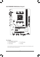
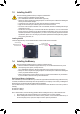
GA-F2A68HM-S1 Motherboard Layout KB_MS VGA ATX_12V FM2+ ATX R_USB CPU_FAN USB_LAN SYS_FAN1 AUDIO BAT Realtek® GbE LAN iTE® Super I/O PCIEX16 PCIEX1 GA-F2A68HM-S1 DDR3_1 SATA3 3 2 CI DDR3_2 R_USB30 M_BIOS AMD A68H PCI CODEC SPDIF_O F_AUDIO CLR_CMOS F_USB2 F_USB1 F_PANEL SATA3 0 1 SYS_FAN2 SPEAKER Box Contents 55 GA-F2A68HM-S1 motherboard 55 Motherboard driver disk 55 User's Manual 55 Two SATA cables 55 I/O Shield The box contents above are for reference only and the actual items shal
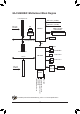
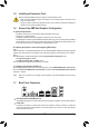
GA-F2A68HM-S1 Motherboard Block Diagram 1 PCI Express x16 APU CLK+/- (100 MHz) PCIe CLK (100 MHz) DISP CLK+/- (100 MHz) LAN RJ45 DDR3 2133/1866/ 1600/1333 MHz AMD APU Realtek® GbE LAN x1 x16 x1 Dual Channel Memory D-Sub PCI Express Bus UMI BIOS 4 SATA 6Gb/s 1 PCI Express x1 PCI Bus 2 USB 3.0/2.0 AMD A68H 8 USB 2.0/1.
Chapter 1 1-1 Hardware Installation Installation Precautions The motherboard contains numerous delicate electronic circuits and components which can become damaged as a result of electrostatic discharge (ESD). Prior to installation, carefully read the user's manual and follow these procedures: •• Prior to installation, make sure the chassis is suitable for the motherboard. •• Prior to installation, do not remove or break motherboard S/N (Serial Number) sticker or warranty sticker provided by your dealer.
1-2 Product Specifications APU FM2+ Socket: - AMD A series processors - AMD Athlon™ series processors (Go to GIGABYTE's website for the latest APU support list.) Chipset AMD A68H Memory 2 x DDR3 DIMM sockets supporting up to 64 GB of system memory Onboard Graphics Audio * Due to a Windows 32-bit operating system limitation, when more than 4 GB of physical memory is installed, the actual memory size displayed will be less than the size of the physical memory installed.
Internal Connectors Back Panel Connectors 1 x front panel header 1 x front panel audio header 1 x S/PDIF Out header 2 x USB 2.0/1.1 headers 1 x speaker header 1 x chassis intrusion header 1 x Clear CMOS jumper 1 x PS/2 keyboard port 1 x PS/2 mouse port 1 x D-Sub port 2 x USB 3.0/2.0 ports 4 x USB 2.0/1.
1-3 Installing the APU Read the following guidelines before you begin to install the APU: •• Make sure that the motherboard supports the APU. (Go to GIGABYTE's website for the latest APU support list.) •• Always turn off the computer and unplug the power cord from the power outlet before installing the APU to prevent hardware damage. •• Locate the pin one of the APU. The APU cannot be inserted if oriented incorrectly. •• Apply an even and thin layer of thermal grease on the surface of the APU.
1-5 Installing an Expansion Card Read the following guidelines before you begin to install an expansion card: •• Make sure the motherboard supports the expansion card. Carefully read the manual that came with your expansion card. •• Always turn off the computer and unplug the power cord from the power outlet before installing an expansion card to prevent hardware damage. 1-6 Setup of the AMD Dual Graphics Configuration A.
USB 2.0/1.1 Port The USB port supports the USB 2.0/1.1 specification. Use this port for USB devices such as a USB keyboard/mouse, USB printer, USB flash drive and etc. USB 3.0/2.0 Port The USB 3.0 port supports the USB 3.0 specification and is compatible to the USB 2.0/1.1 specification. Use this port for USB devices Use this port for USB devices such as a USB keyboard/mouse, USB printer, USB flash drive and etc.
1-8 Internal Connectors 1 2 3 5 12 6 4 10 9 11 7 8 13 4 5 1) ATX_12V 8) F_PANEL 2) ATX 9) F_AUDIO 3) CPU_FAN 10) SPDIF_O 4) SYS_FAN1/SYS_FAN2 11) F_USB1/F_USB2 5) SATA3 0/1/2/3 12) CI 6) BAT 13) SPEAKER 7) CLR_CMOS Read the following guidelines before connecting external devices: •• First make sure your devices are compliant with the connectors you wish to connect. •• Before installing the devices, be sure to turn off the devices and your computer.
1/2) ATX_12V/ATX (2x2 12V Power Connector and 2x12 Main Power Connector) With the use of the power connector, the power supply can supply enough stable power to all the components on the motherboard. Before connecting the power connector, first make sure the power supply is turned off and all devices are properly installed. The power connector possesses a foolproof design. Connect the power supply cable to the power connector in the correct orientation.
DEBUG PORT DEBUG 5) SATA3 0/1/2/3 (SATA 6Gb/sDEBUG Connectors) PORT PORT The SATA connectors conform to SATA 6Gb/s standard and are compatible with SATA 3Gb/s and SATA 1.5Gb/s standard. Each SATA connector supports a single SATA device. The AMD Chipset supports RAID 0, RAID 1, RAID 10, and JBOD. Refer to Chapter 3, "Configuring SATA Hard Drive(s)," for instructions on configuring a RAID array. 1 SATA3 SATA3 0 1 1 7 2 3 Pin No.
8) F_PANEL (Front Panel Header) Connect the power switch, reset switch, and system status indicator on the chassis to this header according to the pin assignments below. Note the positive and negative pins before connecting the cables. Power Switch PLED+ PLEDPW+ PW- Power/Sleep LED 10 9 HD+ HDRESRES+ NC 2 1 Hard Drive Activity LED Reset Switch •• PLED (Power/Sleep LED): Connects to the power status indicator on the System Status LED chassis front panel.
10) SPDIF_O (S/PDIF Out Header) This header supports digital S/PDIF Out and connects a S/PDIF digital audio cable (provided by expansion cards) for digital audio output from your motherboard to certain expansion cards like graphics cards and sound cards.
Chapter 2 BIOS Setup BIOS (Basic Input and Output System) records hardware parameters of the system in the CMOS on the motherboard. Its major functions include conducting the Power-On Self-Test (POST) during system startup, saving system parameters and loading operating system, etc. BIOS includes a BIOS Setup program that allows the user to modify basic system configuration settings or to activate certain system features.
2-2 M.I.T. This section provides information on the BIOS version, CPU base clock, CPU frequency, memory frequency, total memory size, CPU temperature, Vcore, and memory voltage. Whether the system will work stably with the overclock/overvoltage settings you made is dependent on your overall system configurations. Incorrectly doing overclock/overvoltage may result in damage to CPU, chipset, or memory and reduce the useful life of these components.
&& Core Performance Boost (Note 1) Allows you to determine whether to enable the Core Performance Boost (CPB) technology, a CPU performance-boost technology. (Default: Auto) && Turbo Performance Boost Ratio (Note 1) Allows you to determine whether to improve CPU performance. (Default: Disabled) && Core Performance Boost Ratio (Note 1) Allows you alter the ratio for the CPB. The adjustable range is dependent on the CPU being installed.
`` Advanced Memory Settings && Extreme Memory Profile (X.M.P.) (Note), System Memory Multiplier, Memory Frequency(MHz) The settings above are synchronous to those under the same items on the Advanced Frequency Settings menu. && Memory Timing Mode Manual and Advanced Manual allows the Channel Interleaving, Rank Interleaving, and memory timing settings below to be configurable. Options are: Auto (default), Manual, Advanced Manual.
&& CPU Temperature Warning Sets the warning threshold for CPU temperature. When temperature exceeds the threshold, BIOS will emit warning sound. Options are: Disabled (default), 60oC/140oF, 70oC/158oF, 80oC/176oF, 90oC/194oF. && CPU/System Fan Fail Warning Allows the system to emit warning sound if the fan is not connected or fails. Check the fan condition or fan connection when this occurs.
2-3 System Information This section provides information on your motherboard model and BIOS version. You can also select the default language used by the BIOS and manually set the system time. && System Language Selects the default language used by the BIOS. && System Date Sets the system date. The date format is week (read-only), month, date, and year. Use to switch between the Month, Date, and Year fields and use the or key to set the desired value.
2-4 BIOS Features && Boot Option Priorities Specifies the overall boot order from the available devices. For example, you can set hard drive as the first priority (Boot Option #1) and DVD ROM drive as the second priority (Boot Option #2). The list only displays the device with the highest priority for a specific type. For example, only hard drive defined as the first priority on the Hard Drive BBS Priorities submenu will be presented here.
&& Fast Boot Enables or disables Fast Boot to shorten the OS boot process. Ultra Fast provides the fastest bootup speed. (Default: Disabled) && VGA Support Allows you to select which type of operating system to boot. Auto Enables legacy option ROM only. EFI Driver Enables EFI option ROM. (Default) This item is configurable only when Fast Boot is set to Enabled or Ultra Fast. && USB Support Disabled All USB devices are disabled before the OS boot process completes.
&& Storage Boot Option Control Allows you to select whether to enable the UEFI or legacy option ROM for the storage device controller. Disabled Disables option ROM. Legacy Only Enables legacy option ROM only. (Default) UEFI Only Enables UEFI option ROM only. Legacy First Enables legacy option ROM first. UEFI First Enables UEFI option ROM first. This item is configurable only when CSM Support is set to Always.
2-5 Peripherals && IOMMU Enables or disables AMD IOMMU support. (Default: Disabled) && OnChip USB Controller Enables or disables the integrated USB controller. (Default: Enabled) && HD Audio Azalia Device Enables or disables the onboard audio function. (Default: Enabled) If you wish to install a 3rd party add-in audio card instead of using the onboard audio, set this item to Disabled. && Legacy USB Support Allows USB keyboard/mouse to be used in MS-DOS.
`` GFX Configuration && Primary Video Device Specifies the first initiation of the monitor display from the installed PCI Express graphics card or the onboard graphics. IGD Video Sets the onboard graphics as the first display. NB PCIe Slot Video Sets the PCI Express graphics card on the PCI Express slot controlled by the North Bridge as the first display.
2-6 Power Management && Resume by Alarm Determines whether to power on the system at a desired time. (Default: Disabled) If enabled, set the date and time as following: Wake up day: Turn on the system at a specific time on each day or on a specific day in a month. Wake up hour/minute/second: Set the time at which the system will be powered on automatically.
&& Power On Password Set the password when Power On By Keyboard is set to Password. Press on this item and set a password with up to 5 characters and then press to accept. To turn on the system, enter the password and press . Note: To cancel the password, press on this item. When prompted for the password, press again without entering the password to clear the password settings. && Power On By Mouse Allows the system to be turned on by a PS/2 mouse wake-up event.
&& Boot Override Allows you to select a device to boot immediately. Press on the device you select and select Yes to confirm. Your system will restart automatically and boot from that device. && Save Profiles This function allows you to save the current BIOS settings to a profile. You can create up to 8 profiles and save as Setup Profile 1~ Setup Profile 8. Press to complete. Or you can select Select File in HDD/USB/FDD to save the profile to your storage device.
C-1. UEFI RAID Configuration This mode supports Windows 8.1 64-bit installation only. To configure UEFI RAID, you need to prepare a USB flash drive using FAT 32 file format and copy all files (including the UEFI RAID utility rcadm.efi) in the \BootDrv\UEFI RAID Utility folder in your motherboard driver disk to the flash drive. Then follow the steps below. Steps: In BIOS Setup, go to BIOS Features and set Windows 8 Features to Windows 8 and CSM Support to Never. Save the changes and exit BIOS Setup.
2. The selection bar will move to the Disks section on the right of the screen. Select the hard drives to be included in the RAID array. Use the up or down arrow key to select a hard drive and press . The selected hard drive will be shown in green. To use all of the hard drives, simply press to select all. Then press and the selection bar will move to the User Input section on the left bottom of the screen. (Figure 10) 3. First, select a RAID mode and press .
Method B: Steps: 1: Use an alternative system and insert the motherboard driver disk. 2: From your optical drive folder, double click the Menu.exe file in the BootDrv folder. A Command Prompt window will open. 3: Insert the blank formatted disk (if you're using a USB floppy disk drive, make sure it is designated as drive A). Select the controller driver by pressing the corresponding letter from the menu and press . For example, for the AMD A68H, select 6) hseries AHCI/RAIDfor XP.
Regulatory Statements Regulatory Notices This document must not be copied without our written permission, and the contents there of must not be imparted to a third party nor be used for any unauthorized purpose. Contravention will be prosecuted. We believe that the information contained herein was accurate in all respects at the time of printing. GIGABYTE cannot, however, assume any responsibility for errors or omissions in this text.
FCC Notice (U.S.A. Only) This equipment has been tested and found to comply with the limits for a Class B digital device, pursuant to Part 15 of the FCC Rules. These limits are designed to provide reasonable protection against harmful interference in a residential installation. This equipment generates, uses, and can radiate radio frequency energy and, if not installed and used in accordance with the instructions, may cause harmful interference to radio communications.
Contact Us GIGA-BYTE TECHNOLOGY CO., LTD. Address: No.6, Bao Chiang Road, Hsin-Tien Dist., New Taipei City 231,Taiwan TEL: +886-2-8912-4000, FAX: +886-2-8912-4005 Tech. and Non-Tech. Support (Sales/Marketing) : http://esupport.gigabyte.com WEB address (English): http://www.gigabyte.com WEB address (Chinese): http://www.gigabyte.tw You may go to the GIGABYTE website, select your language in the language list on the top right corner of the website.