GA-G41MT-S2PT User's Manual Rev.
Motherboard GA-G41MT-S2PT Dec. 8, 2011 GA-G41MT-S2PT Motherboard Dec.
Copyright © 2011 GIGA-BYTE TECHNOLOGY CO., LTD. All rights reserved. The trademarks mentioned in this manual are legally registered to their respective owners. Disclaimer Information in this manual is protected by copyright laws and is the property of GIGABYTE. Changes to the specifications and features in this manual may be made by GIGABYTE without prior notice.
Table of Contents GA-G41MT-S2PT Motherboard Layout............................................................................5 GA-G41MT-S2PT Motherboard Block Diagram...............................................................6 Chapter 1 Hardware Installation......................................................................................7 1-1 1-2 1-3 1-4 1-5 1-6 1-7 Installation Precautions....................................................................................
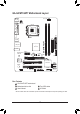
GA-G41MT-S2PT Motherboard Layout CPU_FAN KB_MS ATX_12V VGA LPT COM LGA775 ATX IDE AUDIO Realtek/Atheros GbE LAN PCIEX1 M_BIOS CLR_CMOS PCIEX16 iTE IT8720/ IT8718 B_BIOS BAT DDR3_2 Intel® G41 DDR3_1 USB_LAN GA-G41MT-S2PT R_USB PCI1 Intel® ICH7 CODEC 3 2 1 PCI2 SATA2 F_AUDIO F_PANEL SYS_FAN F_USB1 F_USB2 SATA2 0 Box Contents GA-G41MT-S2PT motherboard Motherboard driver disk User's Manual Two SATA cables I/O Shield * The box contents above are for reference onl
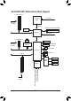
GA-G41MT-S2PT Motherboard Block Diagram 1 PCI Express x16 LGA775 CPU PCIe CLK (100 MHz) Host Interface D-Sub x16 Intel® G41 PCI Express x16 CPU CLK+/(333/266/200 MHz) DDR3 1333(O.C)/1066/800 MHz Dual Channel Memory GMCH CLK (333/266/200 MHz) LAN 1 PCI Express x1 RJ45 Dual BIOS Realtek/Atheros GbE LAN PCIe CLK (100 MHz) x1 PCI Express Bus ATA-100/66/33 IDE Channel x1 4 SATA 3Gb/s Intel® ICH7 8 USB 2.0/1.
Chapter 1 Hardware Installation 1-1 Installation Precautions The motherboard contains numerous delicate electronic circuits and components which can become damaged as a result of electrostatic discharge (ESD). Prior to installation, carefully read the user's manual and follow these procedures: •• Prior to installation, make sure the chassis is suitable for the motherboard.
1-2 Product Specifications CPU Support for an Intel® Core™ 2 Extreme processor/ Intel® Core™ 2 Quad processor/Intel® Core™ 2 Duo processor/ Intel® Pentium® processor/Intel® Celeron® processor in the LGA775 package (Go to GIGABYTE's website for the latest CPU support list.) L2 cache varies with CPU Front Side Bus 1333/1066/800 MHz FSB Memory North Bridge: Intel® G41 Express Chipset South Bridge: Intel® ICH7 2 x 1.
Back Panel Connectors I/O Controller iTE IT8720/IT8718 chip Hardware Monitor BIOS Unique Features 1 x PS/2 keyboard port 1 x PS/2 mouse port 1 x parallel port 1 x serial port 1 x D-Sub port 4 x USB 2.0/1.
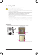
1-3 Installing the CPU Read the following guidelines before you begin to install the CPU: •• Make sure that the motherboard supports the CPU. (Go to GIGABYTE's website for the latest CPU support list.) •• Always turn off the computer and unplug the power cord from the power outlet before installing the CPU to prevent hardware damage. •• Locate the pin one of the CPU. The CPU cannot be inserted if oriented incorrectly.
1-4 Installing the Memory Read the following guidelines before you begin to install the memory: •• Make sure that the motherboard supports the memory. It is recommended that memory of the same capacity, brand, speed, and chips be used. (Go to GIGABYTE's website for the latest supported memory speeds and memory modules.) •• Always turn off the computer and unplug the power cord from the power outlet before installing the memory to prevent hardware damage. •• Memory modules have a foolproof design.
1-6 Back Panel Connectors PS/2 Keyboard and PS/2 Mouse Port Use the upper port (green) to connect a PS/2 mouse and the lower port (purple) to connect a PS/2 keyboard. Parallel Port Use the parallel port to connect devices such as a printer, scanner and etc. The parallel port is also called a printer port. Serial Port Use the serial port to connect devices such as a mouse, modem or other peripherals. D-Sub Port The D-Sub port supports a 15-pin D-Sub connector.
1-7 Internal Connectors 1 3 5 2 11 7 8 6 9 1) 2) 3) 4) 5) 6) ATX_12V ATX CPU_FAN SYS_FAN IDE SATA2 0/1/2/3 4 10 7) 8) 9) 10) 11) BAT F_PANEL F_AUDIO F_USB1/F_USB2 CLR_CMOS Read the following guidelines before connecting external devices: •• First make sure your devices are compliant with the connectors you wish to connect. •• Before installing the devices, be sure to turn off the devices and your computer. Unplug the power cord from the power outlet to prevent damage to the devices.
1/2) ATX_12V/ATX (2x2 12V Power Connector and 2x12 Main Power Connector) With the use of the power connector, the power supply can supply enough stable power to all the components on the motherboard. Before connecting the power connector, first make sure the power supply is turned off and all devices are properly installed. The power connector possesses a foolproof design. Connect the power supply cable to the power connector in the correct orientation.
3/4) CPU_FAN/SYS_FAN (Fan Headers) The motherboard has a 4-pin CPU fan header (CPU_FAN) and a 3-pin system fan header (SYS_FAN). Most fan headers possess a foolproof insertion design. When connecting a fan cable, be sure to connect it in the correct orientation (the black connector wire is the ground wire). The speed control function requires the use of a fan with fan speed control design. For optimum heat dissipation, it is recommended that a system fan be installed inside the chassis. CPU_FAN: Pin No.
PORT DEBUG PORT DEBUG PORT 6) SATA2 0/1/2/3 (SATA 3Gb/s Connectors) The SATA connectors conform to SATA 3Gb/s standard and are compatible with SATA 1.5Gb/s standard. Each SATA connector supports a single SATA device. SATA2 3 2 1 7 1 7 1 7 1 SATA2 7 1 0 Pin No. 1 2 3 4 5 6 7 Definition GND TXP TXN GND RXN RXP GND Please connect the L-shaped end of the SATA cable to your SATA hard drive.
8) F_PANEL (Front Panel Header) Connect the power switch, reset switch, speaker, chassis intrusion switch/sensor and system status indicator on the chassis to this header according to the pin assignments below. Note the positive and negative pins before connecting the cables. G.
9) F_AUDIO (Front Panel Audio Header) The front panel audio header supports Intel High Definition audio (HD) and AC'97 audio. You may connect your chassis front panel audio module to this header. Make sure the wire assignments of the module connector match the pin assignments of the motherboard header. Incorrect connection between the module connector and the motherboard header will make the device unable to work or even damage it. 2 1 10 9 For HD Front Panel Audio: Pin No.
11) CLR_CMOS (Clear CMOS Jumper) Use this jumper to clear the CMOS values (e.g. date information and BIOS configurations) and reset the CMOS values to factory defaults. To clear the CMOS values, use a metal object like a screwdriver to touch the two pins for a few seconds. Open: Normal Short: Clear CMOS Values •• Always turn off your computer and unplug the power cord from the power outlet before clearing the CMOS values.
Chapter 2 BIOS Setup To access the BIOS Setup program, press the key during the POST when the power is turned on. To see more advanced BIOS Setup menu options, you can press + in the main menu of the BIOS Setup program. To upgrade the BIOS, use either the GIGABYTE Q-Flash or @BIOS utility. •• Q-Flash allows the user to quickly and easily upgrade or back up BIOS without entering the operating system.
•• If you do not find the settings you want in the Main Menu or a submenu, press + to access more advanced options. •• When the system is not stable as usual, select the Load Optimized Defaults item to set your system to its defaults. •• The BIOS Setup menus described in this chapter are for reference only and may differ by BIOS version.
CMOS Setup Utility-Copyright (C) 1984-2011 Award Software MB Intelligent Tweaker(M.I.T.) x x x x } CAS Latency Time tRCD tRP tRAS >>>>> Advanced Timing Control Advanced Timing Control ******** Mother Board Voltage Control ******** Voltage Types Normal Current ---------------------------------------------------------------------------->>> CPU CPU Vcore 1.30000V [Auto] CPU Termination 1.200V [Auto] >>> DRAM DRAM Voltage 1.
CPU Host Frequency (Mhz) Allows you to manually set the CPU host frequency. The adjustable range is from 100 MHz to 1200 MHz. This item is configurable only if the CPU Host Clock Control option is enabled. For an 800 MHz FSB CPU, set this item to 200 MHz. For a 1066 MHz FSB CPU, set this item to 266 MHz. For a 1333 MHz FSB CPU, set this item to 333 MHz. Important: It is highly recommended that the CPU frequency be set in accordance with the CPU specifications.
>>>>> Advanced Timing Control Advanced Timing Control CMOS Setup Utility-Copyright (C) 1984-2011 Award Software Advanced Timing Control x x x x x x tRRD tWTR tWR tRFC tRTP Command Rate (CMD) >>>>> Channel A } Channel A Timing Settings } Channel A Driving Settings [Press Enter] [Press Enter] >>>>> Channel B } Channel B Timing Settings } Channel B Driving Settings [Press Enter] [Press Enter] Enter: Select : Move F5: Previous Values
Static tRead Value Options are: Auto (default), 1~15. tRD Phase0 Adjustment Options are: Auto (default), 0-Normal, 1-Advanced. tRD Phase1 Adjustment Options are: Auto (default), 0-Normal, 1-Advanced. tRD Phase2 Adjustment Options are: Auto (default), 0-Normal, 1-Advanced. tRD Phase3 Adjustment Options are: Auto (default), 0-Normal, 1-Advanced. Trd2rd(Different Rank) Options are: Auto (default), 1~15.
Driving Strength Profile Options are: Auto (default). Data Driving Pull-Up Level Options are: Auto (default), +8~-7. Cmd Driving Pull-Up Level Options are: Auto (default), +8~-7. Ctrl Driving Pull-Up Level Options are: Auto (default), +8~-7. Clk Driving Pull-Up Level Options are: Auto (default), +8~-7. Data Driving Pull-Down Level Options are: Auto (default), +8~-7. Cmd Driving Pull-Down Level Options are: Auto (default), +8~-7.
Date (mm:dd:yy) Sets the system date. Time (hh:mm:ss) Sets the system time. IDE Channel 0, 2, 3 Master/Slave IDE Channel 0 Master/Slave, Extended IDE Drive Configure your IDE/SATA devices by using one of the three methods below: •• None If no IDE/SATA devices are used, set this item to None so the system will skip the detection of the device during the POST for faster system startup. •• Auto Lets the BIOS automatically detect IDE/SATA devices during the POST.
Hard Disk Boot Priority Specifies the sequence of loading the operating system from the installed hard drives. Use the up or down arrow key to select a hard drive, then press the plus key <+> (or ) or the minus key <-> (or ) to move it up or down on the list. Press to exit this menu when finished.
CPU Enhanced Halt (C1E) (Note) Enables or disables Intel CPU Enhanced Halt (C1E) function, a CPU power-saving function in system halt state. When enabled, the CPU core frequency and voltage will be reduced during system halt state to decrease power consumption. (Default: Enabled) C2/C2E State Support (Note) Allows you to determine whether to let the CPU enter C2/C2E mode in system halt state.
Init Display First Specifies the first initiation of the monitor display from the installed PCI graphics card, PCI Express graphics card or the onboard VGA. PCI Sets the PCI graphics card as the first display. (Default) Onboard Sets the onboard VGA as the first display. PEG Sets the PCI Express graphics card as the first display. PAVP Mode Enables or disables PAVP mode. Enable this function if you wish to playback HDCP contents.
Onboard H/W LAN Enables or disables the onboard LAN function. (Default: Enabled) If you wish to install a 3rd party add-in network card instead of using the onboard LAN, set this item to Disabled. Onboard LAN Boot ROM Allows you to decide whether to activate the boot ROM integrated with the onboard LAN chip. (Default: Disabled) Onboard Serial Port 1 Enables or disables the first serial port and specifies its base I/O address and corresponding interrupt.
ACPI Suspend Type Specifies the ACPI sleep state when the system enters suspend. S1(POS) Enables the system to enter the ACPI S1 (Power on Suspend) sleep state. In S1 sleep state, the system appears suspended and stays in a low power mode. The system can be resumed at any time. S3(STR) Enables the system to enter the ACPI S3 (Suspend to RAM) sleep state (default).
KB Power ON Password Set the password when Power On by Keyboard is set to Password. Press on this item and set a password with up to 5 characters and then press to accept. To turn on the system, enter the password and press . Note: To cancel the password, press on this item. When prompted for the password, press again without entering the password to clear the password settings.
Reset Case Open Status Keeps or clears the record of previous chassis intrusion status. Enabled clears the record of previous chassis intrusion status and the Case Opened field will show "No" at next boot. (Default: Disabled) Case Opened Displays the detection status of the chassis intrusion detection device attached to the motherboard CI header. If the system chassis cover is removed, this field will show "Yes", otherwise it will show "No".
2-12 Load Optimized Defaults CMOS Setup Utility-Copyright (C) 1984-2011 Award Software MB Intelligent Tweaker(M.I.T.
2-14 Save & Exit Setup CMOS Setup Utility-Copyright (C) 1984-2011 Award Software MB Intelligent Tweaker(M.I.T.
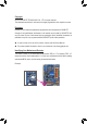
Chapter 3 Drivers Installation •• Before installing the drivers, first install the operating system. •• After installing the operating system, insert the motherboard driver disk into your optical drive. The driver Autorun screen is automatically displayed which looks like that shown in the screen shot below. (If the driver Autorun screen does not appear automatically, go to My Computer, double-click the optical drive and execute the Run.exe program.
Regulatory Statements Regulatory Notices This document must not be copied without our written permission, and the contents there of must not be imparted to a third party nor be used for any unauthorized purpose. Contravention will be prosecuted. We believe that the information contained herein was accurate in all respects at the time of printing. GIGABYTE cannot, however, assume any responsibility for errors or omissions in this text.
- 39 -
Contact Us GIGA-BYTE TECHNOLOGY CO., LTD. Address: No.6, Bao Chiang Road, Hsin-Tien Dist., New Taipei City 231,Taiwan TEL: +886-2-8912-4000, FAX: +886-2-8912-4003 Tech. and Non-Tech. Support (Sales/Marketing) : http://ggts.gigabyte.com.tw WEB address (English): http://www.gigabyte.com WEB address (Chinese): http://www.gigabyte.tw You may go to the GIGABYTE website, select your language in the language list on the top right corner of the website.