GA-H61M-DS2 User's Manual Rev.
Motherboard GA-H61M-DS2 Dec. 4, 2011 GA-H61M-DS2 Motherboard Dec.
Copyright © 2011 GIGA-BYTE TECHNOLOGY CO., LTD. All rights reserved. The trademarks mentioned in this manual are legally registered to their respective owners. Disclaimer Information in this manual is protected by copyright laws and is the property of GIGABYTE. Changes to the specifications and features in this manual may be made by GIGABYTE without prior notice.
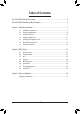
Table of Contents GA-H61M-DS2 Motherboard Layout................................................................................5 GA-H61M-DS2 Motherboard Block Diagram...................................................................6 Chapter 1 Hardware Installation......................................................................................7 1-1 1-2 1-3 1-4 1-5 1-6 1-7 Installation Precautions....................................................................................
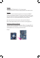
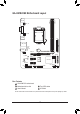
DDR3_1 KB_MS ATX_12V DDR3_2 GA-H61M-DS2 Motherboard Layout VGA LGA1155 CPU_FAN R_USB ATX USB_LAN F_AUDIO M_BIOS BAT 1 0 3 2 PCIEX1_1 B_BIOS CODEC GA-H61M-DS2 PCIEX16 PCIEX1_2 iTE IT8728 AUDIO Atheros/ Realtek GbE LAN SATA2 Intel® H61 SYS_FAN LPT COMA F_USB1 F_USB2 CLR_CMOS F_PANEL Box Contents GA-H61M-DS2 motherboard Motherboard driver disk User's Manual Two SATA cables I/O Shield The box contents above are for reference only and the actual items shall depend on
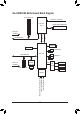
GA-H61M-DS2 Motherboard Block Diagram 1 PCI Express x16 CPU CLK+/- (100 MHz) LGA1155 CPU DDR3 1333/1066/800 MHz Dual Channel Memory DMI 2.0 x16 PCI Express Bus FDI PCIe CLK (100 MHz) Dual BIOS D-Sub 4 SATA 3Gb/s Intel® H61 PCI Express Bus x1 8 USB 2.0/1.
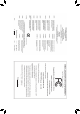
Chapter 1 Hardware Installation 1-1 Installation Precautions The motherboard contains numerous delicate electronic circuits and components which can become damaged as a result of electrostatic discharge (ESD). Prior to installation, carefully read the user's manual and follow these procedures: •• Prior to installation, make sure the chassis is suitable for the motherboard.
1-2 Product Specifications CPU Support for Intel® Core™ i7 processors/Intel® Core™ i5 processors/ Intel® Core™ i3 processors/Intel® Pentium® processors/Intel® Celeron® processors in the LGA1155 package (Go to GIGABYTE's website for the latest CPU support list.) L3 cache varies with CPU Chipset Intel® H61 Express Chipset Memory 2 x 1.
Back Panel Connectors I/O Controller iTE IT8728 chip Hardware Monitor System voltage detection CPU/System temperature detection CPU/System fan speed detection CPU/System fan speed control 2 x 32 Mbit flash Use of licensed AMI EFI BIOS Support for DualBIOS™ PnP 1.0a, DMI 2.0, SM BIOS 2.6, ACPI 2.0a BIOS Bundled Software Operating System Form Factor 1 x PS/2 keyboard port 1 x PS/2 mouse port 1 x D-Sub port 4 x USB 2.0/1.
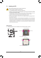
1-3 Installing the CPU Read the following guidelines before you begin to install the CPU: •• Make sure that the motherboard supports the CPU. (Go to GIGABYTE's website for the latest CPU support list.) •• Always turn off the computer and unplug the power cord from the power outlet before installing the CPU to prevent hardware damage. •• Locate the pin one of the CPU. The CPU cannot be inserted if oriented incorrectly.
1-4 Installing the Memory Read the following guidelines before you begin to install the memory: •• Make sure that the motherboard supports the memory. It is recommended that memory of the same capacity, brand, speed, and chips be used. (Go to GIGABYTE's website for the latest supported memory speeds and memory modules.) •• Always turn off the computer and unplug the power cord from the power outlet before installing the memory to prevent hardware damage. •• Memory modules have a foolproof design.
1-6 Back Panel Connectors PS/2 Keyboard and PS/2 Mouse Port Use the upper port (green) to connect a PS/2 mouse and the lower port (purple) to connect a PS/2 keyboard. D-Sub Port The D-Sub port supports a 15-pin D-Sub connector. Connect a monitor that supports D-Sub connection to this port. USB 2.0/1.1 Port The USB port supports the USB 2.0/1.1 specification. Use this port for USB devices such as a USB keyboard/mouse, USB printer, USB flash drive and etc.
1-7 Internal Connectors 1 3 2 12 7 5 4 11 10 1) 2) 3) 4) 5) 6) ATX_12V ATX CPU_FAN SYS_FAN SATA2 0/1/2/3 F_PANEL 9 8 7) 8) 9) 10) 11) 12) 6 F_AUDIO F_USB1/2 COMA LPT CLR_CMOS BAT Read the following guidelines before connecting external devices: •• First make sure your devices are compliant with the connectors you wish to connect. •• Before installing the devices, be sure to turn off the devices and your computer. Unplug the power cord from the power outlet to prevent damage to the devices.
1/2) ATX_12V/ATX (2x2 12V Power Connector and 2x12 Main Power Connector) With the use of the power connector, the power supply can supply enough stable power to all the components on the motherboard. Before connecting the power connector, first make sure the power supply is turned off and all devices are properly installed. The power connector possesses a foolproof design. Connect the power supply cable to the power connector in the correct orientation.
3/4) CPU_FAN/SYS_FAN (Fan Headers) The motherboard has a 4-pin CPU fan header (CPU_FAN) and a 4-pin system fan header (SYS_FAN). Most fan headers possess a foolproof insertion design. When connecting a fan cable, be sure to connect it in the correct orientation (the black connector wire is the ground wire). The speed control function requires the use of a fan with fan speed control design. For optimum heat dissipation, it is recommended that a system fan be installed inside the chassis.
6) F_PANEL (Front Panel Header) Connect the power switch, reset switch, speaker, and system status indicator on the chassis to this header according to the pin assignments below. Note the positive and negative pins before connecting the cables. Power Switch Hard Drive Reset Activity LED Switch F_PANEL (H61M-D2) Power LED Chassis Intrusion Header •• MSG/PWR (Message/Power/Sleep LED): Connects to the power status indicator on the chassis front panel.
7) F_AUDIO (Front Panel Audio Header) The front panel audio header supports Intel High Definition audio (HD) and AC'97 audio. You may connect your chassis front panel audio module to this header. Make sure the wire assignments of the module connector match the pin assignments of the motherboard header. Incorrect connection between the module connector and the motherboard header will make the device unable to work or even damage it. 9 10 1 2 For HD Front Panel Audio: Pin No.
9) COMA (Serial Port Header) The COM header can provide one serial port via an optional COM port cable. For purchasing the optional COM port cable, please contact the local dealer. 9 10 Pin No. 1 2 3 4 5 6 7 8 9 10 1 2 Definition NDCDNSIN NSOUT NDTRGND NDSRNRTSNCTSNRINo Pin DEBUG PORT 10) LPT (Parallel Port Header) The LPT header can provide one parallel port via an optional LPT port cable. For purchasing the optional LPT port cable, please contact the local dealer. 25 26 Pin No.
11) CLR_CMOS (Clear CMOS Jumper) Use this jumper to clear the CMOS values (e.g. date information and BIOS configurations) and reset the CMOS values to factory defaults. To clear the CMOS values, use a metal object like a screwdriver to touch the two pins for a few seconds. Open: Normal Short: Clear CMOS Values •• Always turn off your computer and unplug the power cord from the power outlet before clearing the CMOS values.
Chapter 2 BIOS Setup BIOS (Basic Input and Output System) records hardware parameters of the system in the CMOS on the motherboard. Its major functions include conducting the Power-On Self-Test (POST) during system startup, saving system parameters and loading operating system, etc. BIOS includes a BIOS Setup program that allows the user to modify basic system configuration settings or to activate certain system features.
2-2 The Main Menu On the main menu of the BIOS Setup program, press arrow keys to move among the items and press to accept or enter a sub-menu. Or you can use your mouse to select the item you want. (Sample BIOS Version: E7) Setup Menus Enter Q-Flash Select Default Language Help Function Keys Configuration Items Current Settings BIOS Setup Menus M.I.T. Use this menu to configure the clock, frequency, and voltages of your CPU and memory, etc.
2-3 M.I.T. Whether the system will work stably with the overclock/overvoltage settings you made is dependent on your overall system configurations. Incorrectly doing overclock/overvoltage may result in damage to CPU, chipset, or memory and reduce the useful life of these components. This page is for advanced users only and we recommend you not to alter the default settings to prevent system instability or other unexpected results. (Inadequately altering the settings may result in system's failure to boot.
`` M.I.T. Current Status This screen provides information on CPU/memory frequencies/parameters. `` Advanced Frequency Settings && CPU Clock Ratio Allows you to alter the clock ratio for the installed CPU. The adjustable range is dependent on the CPU being installed. && CPU Frequency Displays the current operating CPU frequency.
&& CPU Clock Ratio, CPU Frequency The settings under the two items above are synchronous to that under the same items on the Advanced Frequency Settings menu. && Internal CPU PLL Overvoltage Enabled allows CPU PLL voltage to operate at a higher value. Disabled allows CPU PLL voltage to operate at default value. Auto lets the BIOS automatically configure this setting.
&& CPU EIST Function (Note) Enables or disables Enhanced Intel SpeedStep Technology (EIST). Depending on CPU loading, Intel EIST technology can dynamically and effectively lower the CPU voltage and core frequency to decrease average power consumption and heat production. Auto lets the BIOS automatically configure this setting. (Default: Auto) && Bi-Directional PROCHOT (Note) Auto Lets BIOS automatically configure this setting.
&& Performance Enhance Allows the system to operate at three different performance levels. Normal Lets the system operate at its basic performance level. Turbo Lets the system operate at its good performance level. (Default) Extreme Lets the system operate at its best performance level. && DRAM Timing Selectable Quick and Expert allows the Channel Interleaving, Rank Interleaving, and memory timing settings below to be configurable. Options are: Auto (default), Quick, Expert.
`` Advanced Voltage Settings && CPU Vtt Allows you to set CPU Vtt voltage. The default is Auto. Allows you to set memory voltage. The default is Auto.
&& Reset Case Open Status Disabled Keeps or clears the record of previous chassis intrusion status. (Default) Enabled Clears the record of previous chassis intrusion status and the Case Opened field will show "No" at next boot. && Case Opened Displays the detection status of the chassis intrusion detection device attached to the motherboard CI header. If the system chassis cover is removed, this field will show "Yes", otherwise it will show "No".
`` Miscellaneous Settings && Isochronous Support Determines whether to enable specific streams within the CPU and Chipset. This item is present only when you install a CPU that supports this feature. For more information about Intel CPUs' unique features, please visit Intel's website. (Default: Enabled) 2-4 System This section provides information on your motherboard model, and BIOS version. You can also select the default language used by the BIOS and manually set the system time.
&& System Language Selects the default language used by the BIOS. Sets the system date. The date format is week (read-only), month, date, and year. Use to switch between the Month, Date, and Year fields and use the up arrow or down arrow key to set the desired value. && System Date && System Time Sets the system time. The time format is hour, minute, and second. For example, 1 p.m. is 13:0:0.
Or if you want to install an operating system that supports GPT partitioning such as Windows 7 64-bit, select the optical drive that contains the Windows 7 64-bit installation disk and is prefixed with "UEFI:" string. && Hard Drive/CD/DVD ROM Drive/Floppy Drive/Network Device BBS Priorities Specifies the boot order for a specific device type, such as hard drives, optical drives, floppy disk drives, and devices that support Boot from LAN function, etc.
2-6 Peripherals && LAN PXE Boot Option ROM Allows you to decide whether to activate the boot ROM integrated with the onboard LAN chip. (Default: Disabled) && SATA Controller(s) (Intel H61 Chipset) Enables or disables the integrated SATA controllers. (Default: Enabled) Allows you to decide whether to configure the SATA controller integrated in the Intel H61 Chipset to AHCI mode. IDE Configures the SATA controller to IDE mode. (Default) AHCI Configures the SATA controller to AHCI mode.
&& Internal Graphics Memory Size Allows you to set the onboard graphics memory size. Options are: 32M~1024M. (Default: 64M) Allows you to allocate the DVMT memory size of the onboard graphics. Options are: 128M, 256M, MAX. (Default: 256M) && DVMT Total Memory Size && Legacy USB Support Allows USB keyboard/mouse to be used in MS-DOS. (Default: Enabled) Determines whether to enable EHCI Hand-off feature for an operating system without EHCI Hand-off support.
&& AC BACK Determines the state of the system after the return of power from an AC power loss. Memory The system returns to its last known awake state upon the return of the AC power. Always On The system is turned on upon the return of the AC power. Always Off The system stays off upon the return of the AC power. (Default) && Power On By Keyboard Allows the system to be turned on by a PS/2 keyboard wake-up event.
&& Internal Graphics Deep Standby Mode Allows you to determine whether to let the onboard graphics enter deeper standby mode. (Default: Disabled) 2-8 Save & Exit && Save & Exit Setup Press on this item and select Yes. This saves the changes to the CMOS and exits the BIOS Setup program. Select No or press to return to the BIOS Setup Main Menu. && Exit Without Saving Press on this item and select Yes.
Chapter 3 Drivers Installation •• Before installing the drivers, first install the operating system. •• After installing the operating system, insert the motherboard driver disk into your optical drive. The driver Autorun screen is automatically displayed which looks like that shown in the screen shot below. (If the driver Autorun screen does not appear automatically, go to My Computer, double-click the optical drive and execute the Run.exe program.
Regulatory Statements Regulatory Notices This document must not be copied without our written permission, and the contents there of must not be imparted to a third party nor be used for any unauthorized purpose. Contravention will be prosecuted. We believe that the information contained herein was accurate in all respects at the time of printing. GIGABYTE cannot, however, assume any responsibility for errors or omissions in this text.
- 38 -
- 39 -
Contact Us GIGA-BYTE TECHNOLOGY CO., LTD. Address: No.6, Bao Chiang Road, Hsin-Tien Dist., New Taipei City 231,Taiwan TEL: +886-2-8912-4000, FAX: +886-2-8912-4003 Tech. and Non-Tech. Support (Sales/Marketing) : http://ggts.gigabyte.com.tw WEB address (English): http://www.gigabyte.com WEB address (Chinese): http://www.gigabyte.tw You may go to the GIGABYTE website, select your language in the language list on the top right corner of the website.