GA-J1900N-D3V User's Manual Rev.
Motherboard GA-J1900N-D3V Motherboard GA-J1900N-D3V Jan. 3, 2014 Jan. 3, 2014 Copyright © 2014 GIGA-BYTE TECHNOLOGY CO., LTD. All rights reserved. The trademarks mentioned in this manual are legally registered to their respective owners. Disclaimer Information in this manual is protected by copyright laws and is the property of GIGABYTE. Changes to the specifications and features in this manual may be made by GIGABYTE without prior notice.
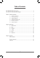
Table of Contents GA-J1900N-D3V Motherboard Layout.............................................................................4 GA-J1900N-D3V Motherboard Block Diagram................................................................5 Chapter 1 Hardware Installation......................................................................................6 1-1 1-2 1-3 1-4 1-5 1-6 Installation Precautions.................................................................................... 6 Product Specifications.
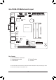
GA-J1900N-D3V Motherboard Layout F_PANEL DEBUG_PORT KB_MS LPT ATX_12V ATX SYS_FAN COMA COMB CI iTE® Super I/O CLR_CMOS BAT VGA DVI CPU_FAN Realtek® GbE LAN SODIMM_1 SODIMM_2 Intel® J1900 SoC USB30_LAN2 USB30_LAN1 Realtek® GbE LAN Renesas® uPD720210 F_AUDIO SPDIF_O AUDIO SATA2 0 1 M_BIOS PCIe to PCI B_BIOS Bridge CODEC GA-J1900N-D3V F_USB MINI PCIE BUZZER PCI Box Contents 55 GA-J1900N-D3V motherboard 55 Motherboard driver disk 55 User's Manual 55 Two SATA cables 55 I/O Shield
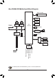
GA-J1900N-D3V Motherboard Block Diagram DDR3L 1333 MHz Dual Channel Memory D-Sub LAN RJ45 RJ45 Realtek® GbE LAN Realtek® GbE LAN x1 x1 x1 x1 PCI Express Bus DVI-D Dual BIOS Intel® J1900 SoC 2 SATA 3Gb/s Renesas® uPD720210 Hub PCIe to PCI Bridge 4 USB 3.0/2.0 2 USB 2.0/1.1 Mini PCI Express x1 LPC Bus iTE® Super I/O S/PDIF Out 1 PCI PCI CLK (33 MHz) For detailed product information/limitation(s), refer to "1-2 Product Specifications.
Chapter 1 1-1 Hardware Installation Installation Precautions The motherboard contains numerous delicate electronic circuits and components which can become damaged as a result of electrostatic discharge (ESD). Prior to installation, carefully read the user's manual and follow these procedures: •• Prior to installation, make sure the chassis is suitable for the motherboard. •• Prior to installation, do not remove or break motherboard S/N (Serial Number) sticker or warranty sticker provided by your dealer.
1-2 Product Specifications CPU Built in with an Intel® Celeron® Quad-Core J1900 SoC (2.0 GHz) Memory 2 MB Cache 2 x 1.35V DDR3L DIMM sockets supporting up to 8 GB of system memory Dual channel memory architecture Support for DDR3L 1333 MHz memory modules Support for non-ECC memory modules (Go to GIGABYTE's website for the latest supported memory speeds and memory modules.
Internal Connectors 1 x parallel port header 1 x Clear CMOS jumper 1 x chassis intrusion header 1 x debug card header 1 x PS/2 keyboard port 1 x PS/2 mouse port 1 x D-Sub port 1 x DVI-D port 2 x serial ports 4 x USB 3.0/2.
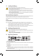
1-3 Installing the Memory Read the following guidelines before you begin to install the memory: •• Make sure that the motherboard supports the memory. It is recommended that memory of the same capacity, brand, speed, and chips be used. (Go to GIGABYTE's website for the latest supported memory speeds and memory modules.) •• Always turn off the computer and unplug the power cord from the power outlet before installing the memory to prevent hardware damage. •• Memory modules have a foolproof design.
DVI-D Port (Note) The DVI-D port conforms to the DVI-D specification and supports a maximum resolution of 1920x1080 (the actual resolutions supported depend on the monitor being used). Connect a monitor that supports DVI-D connection to this port. Dual Display Configurations for the Onboard Graphics: Dual-display configurations are supported after you install motherboard drivers in OS, but not during the BIOS Setup or POST process.
1-6 Internal Connectors 10 14 1 4 6 2 13 12 9 11 3 7 8 5 1) 2) 3) 4) 5) 6) 7) ATX_12V ATX CPU_FAN SYS_FAN SATA2 0/1 F_PANEL F_AUDIO 8) 9) 10) 11) 12) 13) 14) SPDIF_O F_USB LPT BAT CLR_CMOS CI DEBUG_PORT Read the following guidelines before connecting external devices: •• First make sure your devices are compliant with the connectors you wish to connect. •• Before installing the devices, be sure to turn off the devices and your computer.
1/2) ATX_12V/ATX (2x2 12V Power Connector and 2x12 Main Power Connector) With the use of the power connector, the power supply can supply enough stable power to all the components on the motherboard. Before connecting the power connector, first make sure the power supply is turned off and all devices are properly installed. The power connector possesses a foolproof design. Connect the power supply cable to the power connector in the correct orientation.
5) SATA2 0/1 (SATA 3Gb/s Connectors) The SATA connectors conform to SATA 3Gb/s standard and are compatible with SATA 1.5Gb/s standard. Each SATA connector supports a single SATA device. SATA2 Pin No. 1 2 3 4 5 6 7 0 1 1 1 7 7 Definition GND TXP TXN GND RXN RXP GND 6) F_PANEL (Front Panel Header) Connect the power switch, reset switch, and system status indicator on the chassis to this header according to the pin assignments below. Note the positive and negative pins before connecting the cables.
7) F_AUDIO (Front Panel Audio Header) The front panel audio header supports Intel High Definition audio (HD) and AC'97 audio. You may connect your chassis front panel audio module to this header. Make sure the wire assignments of the module connector match the pin assignments of the motherboard header. Incorrect connection between the module connector and the motherboard header will make the device unable to work or even damage it. 9 1 10 2 For HD Front Panel Audio: Pin No.
10) LPT (Parallel Port Header) The LPT header can provide one parallel port via an optional LPT port cable. For purchasing the optional LPT port cable, please contact the local dealer. 25 1 26 2 Pin No. 1 2 3 4 5 6 7 8 9 10 11 12 13 Definition STBAFDPD0 ERRPD1 INITPD2 SLINPD3 GND PD4 GND PD5 Pin No.
12) CLR_CMOS (Clear CMOS Jumper) Use this jumper to clear the BIOS configuration and reset the CMOS values to factory defaults. To clear the CMOS values, use a metal object like a screwdriver to touch the two pins for a few seconds. Open: Normal Short: Clear CMOS Values •• Always turn off your computer and unplug the power cord from the power outlet before clearing the CMOS values.
Chapter 2 BIOS Setup BIOS (Basic Input and Output System) records hardware parameters of the system in the CMOS on the motherboard. Its major functions include conducting the Power-On Self-Test (POST) during system startup, saving system parameters and loading operating system, etc. BIOS includes a BIOS Setup program that allows the user to modify basic system configuration settings or to activate certain system features.
2-2 Main Once you enter the BIOS Setup program, the Main Menu (as shown below) appears on the screen. Use arrow keys to move among the items and press to accept or enter a sub-menu. Main Menu Help The on-screen description of a highlighted setup option is displayed on the bottom line of the Main Menu. Submenu Help While in a submenu, press to display a help screen (General Help) of function keys available for the menu. Press to exit the help screen.
2-3 Advanced Aptio Setup Utility - Copyright (C) 2013 American Megatrends, Inc.
&& ErP Determines whether to let the system consume least power in S5 (shutdown) state. (Default: Disabled) Note: When this item is set to Enabled, the following functions will become unavailable: PME event wake up, power on by mouse, power on by keyboard, and wake on LAN. && Case Open Displays the detection status of the chassis intrusion detection device attached to the motherboard CI header. If the system chassis cover is removed, this field will show "Open", otherwise it will show "Close.
`` PPM Configuration && EIST Enables or disables Enhanced Intel® Speed Step Technology (EIST). Depending on CPU loading, Intel EIST technology can dynamically and effectively lower the CPU voltage and core frequency to decrease average power consumption and heat production. (Default: Enabled) && CPU C state Report Enables or disables support for CPU's power-saving functions.
`` Network Stack Configuration && Network Stack Disables or enables booting from the network to install a GPT format OS, such as installing the OS from the Windows Deployment Services server. (Default: Disabled) && Ipv4 PXE Support Enables or disables IPv4 PXE Support. This item is configurable only when Network Stack is enabled. && Ipv6 PXE Support Enables or disables IPv6 PXE Support. This item is configurable only when Network Stack is enabled.
&& Other PCI devices Allows you to select whether to enable the UEFI or Legacy option ROM for the PCI device controller other than the LAN, storage device, and graphics controllers. UEFI First Enables UEFI option ROM first. (Default) Legacy only Enables legacy option ROM only. This item is configurable only when CSM Support is set to Enabled. `` USB Configuration && Legacy USB Support Allows USB keyboard/mouse to be used in MS-DOS. (Default: Enabled) && USB3.
2-4 Chipset Aptio Setup Utility - Copyright (C) 2013 American Megatrends, Inc. Main Advanced Chipset Security Boot Save & Exit Realtek LAN Controller [Enabled] Realtek LAN 2 Controller [Enabled] `` North Bridge `` South Bridge gf: Select Screen hi: Select Item Enter: Select +/-: Change Opt. F1: General Help F2: Previous Values F3: Optimized Defaults F4: Save & Exit ESC: Exit Aptio Setup Utility - Copyright (C) 2013 American Megatrends, Inc.
&& High Precision Timer Enables or disables High Precision Event Timer (HPET) in the operating system. (Default: Enabled) && Restore AC Power Loss Determines the state of the system after the return of power from an AC power loss. Power Off The system stays off upon the return of the AC power. (Default) Power On The system is turned on upon the return of the AC power. Last State The system returns to its last known awake state upon the return of the AC power.
To cancel the password, press on the password item and when requested for the password, enter the correct one first. When prompted for a new password, press without entering any password. Press again when prompted to confirm. && HDD Security Configuration Displays a list of connected hard drives and allows you to set a password for a specific hard drive. This item appears only when a hard drive is installed. `` Secure Boot menu && System Mode Displays the current system mode.
&& Setup Prompt Timeout Allows you to configure the number of seconds to stay in BIOS setup prompt screen. (Default: 6) && Bootup NumLock State Enables or disables Numlock feature on the numeric keypad of the keyboard after the POST. (Default: On) && Full Screen LOGO Show Allows you to determine whether to display the GIGABYTE Logo at system startup. Disabled skips the GIGABYTE Logo when the system starts up.
2-7 Save & Exit Aptio Setup Utility - Copyright (C) 2013 American Megatrends, Inc. Main Advanced Chipset Security Boot Save & Exit Save Changes and Reset Save Changes and Reset Restore Defaults Save as User Defaults Restore User Defaults Boot Override UEFI: USB 2.0 USB Flash Drive 0.00 UEFI: Built-in EFI Shell Launch EFI Shell from filesystem device gf: Select Screen hi: Select Item Enter: Select +/-: Change Opt.
Chapter 3 Appendix Drivers Installation •• Before installing the drivers, first install the operating system. (The following instructions use Windows 8 as the example operating system.) •• After installing the operating system, insert the motherboard driver disk into your optical drive. Click on the message "Tap to choose what happens with this disc" on the top-right corner of the screen and select "Run Run.exe." (Or go to My Computer, double-click the optical drive and execute the Run.exe program.
Regulatory Statements Regulatory Notices This document must not be copied without our written permission, and the contents there of must not be imparted to a third party nor be used for any unauthorized purpose. Contravention will be prosecuted. We believe that the information contained herein was accurate in all respects at the time of printing. GIGABYTE cannot, however, assume any responsibility for errors or omissions in this text.
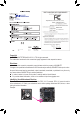
FCC Notice (U.S.A. Only) This equipment has been tested and found to comply with the limits for a Class B digital device, pursuant to Part 15 of the FCC Rules. These limits are designed to provide reasonable protection against harmful interference in a residential installation. This equipment generates, uses, and can radiate radio frequency energy and, if not installed and used in accordance with the instructions, may cause harmful interference to radio communications.
Contact Us GIGA-BYTE TECHNOLOGY CO., LTD. Address: No.6, Bao Chiang Road, Hsin-Tien Dist., New Taipei City 231,Taiwan TEL: +886-2-8912-4000, FAX: +886-2-8912-4005 Tech. and Non-Tech. Support (Sales/Marketing) : http://ggts.gigabyte.com.tw WEB address (English): http://www.gigabyte.com WEB address (Chinese): http://www.gigabyte.tw You may go to the GIGABYTE website, select your language in the language list on the top right corner of the website.