GA-K8NS Ultra-939 AMD Socket 939 Processor Motherboard User's Manual Rev. 1002 12ME-K8NSU939-1002 Copyright © 2004 GIGABYTE TECHNOLOGY CO., LTD Copyright by GIGA-BYTE TECHNOLOGY CO., LTD. ("GBT"). No part of this manual may be reproduced or transmitted in any from without the expressed, written permission of GBT. Trademarks Third-party brands and names are the property of their respective owners. Notice Please do not remove any labels on motherboard, this may void the warranty of this motherboard.
Mother Board GA-K8NS Ultra-939 Oct.
Motherboard GA-K8NS Ultra-939 Oct.
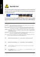
English Read Me First! When you installing AGP card, please make sure the following notice is fully understood and practiced. If your AGP card has "AGP 4X/8X (1.5V) notch" (show below), please make sure your AGP card is AGP 4X/8X. AGP 4X/8X notch Caution: AGP 2X card is not supported by nVIDIA® nForce3 Ultra. You might experience system unable to boot up normally. Please insert an AGP 4X/8X card.
Computer motherboards and expansion cards contain very delicate Integrated Circuit (IC) chips. To protect them against damage from static electricity, you should follow some precautions whenever you work on your computer. 1. Unplug your computer when working on the inside. 2. Use a grounded wrist strap before handling computer components. If you do not have one, touch both of your hands to a safely grounded object or to a metal object, such as the power supply case. 3.
English Table of Contents Read Me First! ........................................................................................ 4 Chapter 1 Introduction ............................................................................ 8 Features Summary ...................................................................................... 8 GA-K8NS Ultra-939 Motherboard Layout ................................................. 10 Block Diagram ...................................................................
Select Language ....................................................................................... 51 Load Optimized Defaults ........................................................................... 52 Set Supervisor/User Password .................................................................. 52 Exit Without Saving .................................................................................... 53 Save & Exit Setup .............................................................................
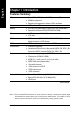
English Chapter 1 Introduction Features Summary CPU Chipset y Socket 939 for AMD Althlon™ 64 / 64FX processor (K8) y 2000MHz system bus y Supports core frequencies in excess of 3000+ and faster y nVIDIA® nForce3 Ultra TM Memory y 4 184-pin DDR DIMM sockets, support up to 4GB DRAM (Max.)(Note 1) y Supports Dual Channel DDR400/333/266/200 DIMM Slots y 1 AGP slot supports 8X/4X(1.
y ALC850 CODEC (UAJ) y y y y English Onboard Audio Supports Jack Sensing function Supports 2 / 4 / 6 / 8 channel audio Supports Line In/ Line Out/ MIC connection Surround Back Speaker (by optional Surround-Kit) y y Onboard SATA RAID y (SATA0_SB, SATA1_SB) y SPDIF In / Out CD In / Game connector Onboard nVIDIA® nForce3 Ultra chipset Supports data striping (RAID 0) or mirroring (RAID 1) function y y On-Board SATA RAID y (SATA0_SII, SATA1_SII) y Supports data transfer rate of up 150 MB Supports a maximu
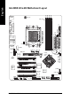
DDR3 DDR4 DDR1 DDR2 ATX_12V KB_MS USB LAN2 USB AUDIO SOCKET 939 CPU_FAN PWR_FAN IDE1 IDE2 (10/100) GA-K8NS Ultra-939 COMB LPT ATX COMA RAM_LED LAN1 (Gigabit Ethernet) FDD ICS1883 F_AUDIO SUR_CEN SATA0_SB SATA1_SB BAT 2X_DET CD_IN nVIDIA® nForce ™ 3 Ultra IT8712 AGP PCI1 CLR_CMOS BACKUP BIOS CODEC MAIN BIOS PCI2 IR_CIR PCI3 TSB82AA2 Marvell 8001 F_PANEL PCI4 TSB81BA3 SiI3512 PWR_LED PCI5 GAME INFO_LINK SPDIF_IO GA-K8NS Ultra-939 Motherboard NB_FAN English GA-K8N
English Block Diagram AMD K8 Socket 939 CPU AGP Slot 4X/8X AGPCLK (66MHz) CPUCLK+/- (800MHz) DDR400/DDR333/266/200 DIMM HyperTransport Bus LAN1 LAN2 RJ45 RJ45 Unbuffered DIMMs BIOS nVIDIA nForce 3 Game Port LPC BUS TM 5 PCI Marvell 8001 IT8712 Ultra AC97 Link ICS 1883 Floppy LPT Port PS/2 KB/Mouse 24 MHz 33 MHz TSB82AA2 2 COM Ports SiI3512 TSB81BA3 2 Serial ATA LINE-OUT 3 IEEE1394b 8 USB Ports MIC LINE-IN AC97 CODEC 2 Serial ATA PCICLK (33MHz) IR_CIR ATA33/66/100/133 IDE C
English GA-K8NS Ultra-939 Motherboard - 12 -
English Chapter 2 Hardware Installation Process To set up your computer, you must complete the following steps: Step 1 - Install the Central Processing Unit (CPU) Step 2 - Install Memory Modules Step 3 - Install Expansion Cards Step 4 - Install I/O Peripherals Cables Step 4 Step 1 Step 2 Step 4 Step 4 Step 3 Congratulations! You have accomplished the hardware installation! Turn on the power supply or connect the power cable to the power outlet. Continue with the BIOS/software installation.
English Step 1: Install the Central Processing Unit (CPU) Before installing the processor and cooling fan, adhere to the following warning: 1. Please make sure the CPU type is supported by the motherboard. 2. The processor will overheat without the heatsink and/or fan, resulting in permanent irreparable damage. 3. If you do not match the CPU socket Pin 1 and CPU cut edge well, it will cause improper installation. Please change the insert orientation. 4.
Figure 3. Application of thermal grease to the processor. Step 1-3.Once the thermal grease has been applied to the processor, the heatsink can be attached to the processor. Align the heatsink assembly with the support frame mating with the backer plate standoffs as shown in Figure 4 & 5. Figure 4 & 5. Alignment of heatsink assembly with standoffs. Step 1-4. Connect the fan power wires to the header on the motherboard as shown in Figure 6. Figure 6. Connecting the fan power wires.
English Step 2: Install Memory Modules Before installing the memory modules, adhere to the following warning: 1. When RAM LED is ON, do not install / remove DIMM from socket. 2. Please note that the DIMM module can only fit in one direction due to the notch. Wrong orientation will cause improper installation. Please change the insert orientation. The motherboard has 4 dual inline memory module (DIMM) sockets. The BIOS will automatically detects memory type and size.
GA-K8NS Ultra-939 supports Dual Channel Technology. When Dual Channel Technology is activated, the bandwidth of memory bus will be double the original one,with the fastest speed at 6.4GB/s(DDR400) or 5.3GB/s(DDR333). GA-K8NS Ultra-939 includes four DIMM slots, and each Channel has 2 DIMMs as following: Channel A : DDR 1, DDR 3 Channel B : DDR 2, DDR 4 Below are the explanations: 1.
English Step 3: Install Expansion Cards 1. Read the related expansion card's instruction document before install the expansion card into the computer. 2. Remove your computer's chassis cover, screws and slot bracket from the computer. 3. Press the expansion card firmly into expansion slot in motherboard. 4. Be sure the metal contacts on the card are indeed seated in the slot. 5. Replace the screw to secure the slot bracket of the expansion card. 6. Replace your computer's chassis cover. 7.
English Step 4: Install I/O Peripherals Cables Step 4-1: I/O Back Panel Introduction PS/2 Keyboard and PS/2 Mouse Connector PS/2 Mouse Connector (6 pin Female) This connector supports standard PS/2 keyboard and PS/2 mouse. PS/2 Keyboard Connector (6 pin Female) Parallel Port, Serial Ports (COMA / COMB) Parallel Port (25 pin Female) COMA This connector supports 2 standard COM ports and 1 Parallel port. Devices like printer can be connected to Parallel port; mouse and modem etc.
English / USB/LAN Connector LAN2 Before you connect your device(s) into USB connector(s), please make sure your device(s) such as USB keyboard,mouse, scanner, zip, speaker...etc. Have a standard USB interface. Also make sure your OS supports USB controller. If your OS does not support USB controller, please contact OS vendor for possible patch or driver upgrade. For more information please contact your OS or device(s) vendors. LAN1 connector is fast Ethernet with 10/100/ 1000 Mbps speed.
1 9 14 English Step 4-2: Connectors Introduction 5 2 8 7 3 15 16 19 25 6 17 16 22 13 12 4 23 18 24 21 10 20 1) ATX_12V 14) RAM_LED 2) 3) 4) 5) ATX (Power Connector) CPU_FAN SYS_FAN PWR_FAN 15) 16) 17) 18) 2X_DET F_AUDIO SUR_CEN SPDIF_IO 6) 7) 8) 9) NB_FAN FDD IDE1 / IDE2 SATA0_SB / SATA1_SB; 19) 20) 21) 22) CD_IN F_USB1 / F_USB2 F1_1394 / F2_1394 IR_CIR 10) 11) 12) 13) SATA0_SII / SATA1_SII BATTERY F_PANEL PWR_LED 23) GAME 24) INFO_LINK 25) CLR_CMOS - 21 - Hardware Installatio
English 1/2) ATX_12V / ATX (Power Connector) With the use of the power connector, the power supply can supply enough stable power to all the components on the motherboard. Before connecting the power connector, please make sure that all components and devices are properly installed. Align the power connector with its proper location on the motherboard and connect tightly. The ATX_12V power connector mainly supplies power to the CPU.
The cooler fan power connector supplies a +12V power voltage via a 3-pin power connector and possesses a foolproof connection design. Most coolers are designed with color-coded power connector wires. A red power connector wire indicates a positive connection and requires a +12V power voltage. The black connector wire is the ground wire(GND). Please remember to connect the power to the cooler to prevent system overheating and failure.
English 7) FDD (Floppy Connector) The FDD connector is used to connect the FDD cable while the other end of the cable connects to the FDD drive. The types of FDD drives supported are: 360KB, 720KB, 1.2MB, 1.44MB and 2.88MB. Please connect the red power connector wire to the pin1 position. 34 33 2 1 8) IDE1 / IDE2 (IDE Connector) An IDE device connects to the computer via an IDE connector.
Serial ATA can provide 150MB/s transfer rate. Please refer to the BIOS setting for the Serial ATA and install the proper driver in order to work properly. 1 7 SATA0_SB / SATA1_SB 7 1 Pin No. Definition 1 GND 2 TXP 3 4 TXN GND 5 RXN 6 RXP 7 GND SATA0_SII / SATA1_SII The SATA0_SII / SATA1_SII connectors support hot plug function. 11) BATTERY CAUTION Danger of explosion if battery is incorrectly replaced. Replace only with the same or equivalent type recommended by the manufacturer.
English 12) F_PANEL (Front Panel Jumper) Please connect the power LED, PC speaker, reset switch and power switch etc. of your chassis front panel to the F_PANEL connector according to the pin assignment below.
PWR_LED is connect with the system power indicator to indicate whether the system is on/off. It will blink when the system enters suspend mode. If you use dual color LED, power LED will turn to another color. 1 Pin No. Definition 1 MPD+ 2 MPD- 3 MPD- 14) RAM_LED Do not remove memory modules while RAM_LED is on. It might cause short or other unexpected damages due to the stand by voltage. Remove memory modules only when AC power cord is disconnected.
When an AGP 2X (3.3V) card is installed the 2X_DET will light up, indicating a non-supported graphics card is inserted. Informing users that system might not boot up normally due to AGP 2X (3.3V) is not supported by the chipset. + _ English 15) 2X_LED 16) F_AUDIO (Front Audio Connector) If you want to use Front Audio connector, you must remove 5-6, 9-10 Jumper. In order to utilize the front audio header, your chassis must have front audio connector.
English 17) SUR_CEN (Surround Center Connector) Please contact your nearest dealer for optional SUR_CEN cable. 8 2 7 1 Pin No. 1 Definition SUR OUTL 2 SUR OUTR 3 GND 4 5 No Pin CENTER_OUT 6 BASS_OUT 7 AUX_L 8 AUX_R 18) SPDIF_IO (SPDIF In / Out Connector) The SPDIF output is capable of providing digital audio to external speakers or compressed AC3 data to an external Dolby Digital Decoder. Use this feature only when your stereo system has digital input and output function.
English 19) CD_IN (CD In Connector) Connect CD-ROM or DVD-ROM audio out to the CD_IN connector. 1 Pin No. 1 Definition CD-L 2 GND 3 GND 4 CD-R 20) F_USB1 / F_USB2 (Front USB Connector) Be careful with the polarity of the front USB connector. Check the pin assignment carefully while you connect the front USB cable, incorrect connection between the cable and connector will make the device unable to work or even damage it. For optional front USB cable, please contact your local dealer.
Serial interface standard set by Institute of Electrical and Electronics Engineers, which has features like high speed, highbandwidth and hot plug. Be careful with the polarity of the IEEE1394 connector. Check the pin assignment carefully while you connect the IEEE1394 cable, incorrect connection between the cable and connector will make the device unable to work or even damage it. For optional IEEE1394 cable, please contact your local dealer. F2_1394 2 1 F1_1394 2 10 9 1 Pin No.
English 23) GAME (Game Connector) This connector supports joystick, MIDI keyboard and other relate audio devices. Check the pin assignment while you connect the game cables. Please contact your nearest dealer for optional game cables. Pin No.
You may clear the CMOS data to its default values by this jumper. To clear CMOS, temporarily short 1-2 pin. Default doesn't include the "Shunter" to prevent from improper use this jumper.
English GA-K8NS Ultra-939 Motherboard - 34 -
BIOS Setup is an overview of the BIOS Setup Program. The program that allows users to modify the basic system configuration. This type of information is stored in battery-backed CMOS RAM so that it retains the Setup information when the power is turned off. ENTERING SETUP Powering ON the computer and pressing immediately will allow you to enter Setup. If you require more advanced BIOS settings, please go to "Advanced BIOS" setting menu.
English Main Menu The on-line description of the highlighted setup function is displayed at the bottom of the screen. Status Page Setup Menu / Option Page Setup Menu Press F1 to pop up a small help window that describes the appropriate keys to use and the possible selections for the highlighted item. To exit the Help Window press . The Main Menu (For example: BIOS Ver. : E1) Once you enter Award BIOS CMOS Setup Utility, the Main Menu (as figure below) will appear on the screen.
English z PC Health Status This setup page is the System auto detect Temperature, voltage, fan, speed. z MB Intelligent Tweaker(M.I.T.) This setup page is control CPU's clock and frequency ratio. z Top Performance If you wish to maximize the performance of your system, set "Top Performance" as "Enabled". z Select Language This setup page is select multi-language.
English Standard CMOS Features CMOS Setup Utility-Copyright (C) 1984-2004 Award Software Standard CMOS Features ` ` ` ` ` ` Date (mm:dd:yy) Time (hh:mm:ss) Wed, May 19 2004 22:31:24 IDE Channel 0 Master IDE Channel 0 Slave IDE Channel 1 Master IDE Channel 1 Slave IDE Channel 2 Master IDE Channel 3 Master [None] [None] [None] [None] [None] [None] Drive A Drive B Floppy 3 Mode Suport [1.44M, 3.
The category identifies the types of floppy disk drive A or drive B that has been installed in the computer. None No floppy drive installed 360K, 5.25" 5.25 inch PC-type standard drive; 360K byte capacity. 1.2M, 5.25" 5.25 inch AT-type high-density drive; 1.2M byte capacity (3.5 inch when 3 Mode is Enabled). 720K, 3.5" 3.5 inch double-sided drive; 720K byte capacity 1.44M, 3.5" 3.5 inch double-sided drive; 1.44M byte capacity. 2.88M, 3.5" 3.5 inch double-sided drive; 2.88M byte capacity.
English Advanced BIOS Features CMOS Setup Utility-Copyright (C) 1984-2004 Award Software Advanced BIOS Features ` Hard Disk Boot Priority First Boot Device Second Boot Device Third Boot Device Boot Up Floopy Seek Password Check Flexible AGP 8X Init Display First [Press Enter] [Floppy] [Hard Disk] [CDROM] [Disabled] [Setup] [Auto] [AGP] KLJI: Move Enter: Select +/-/PU/PD: Value F10: Save F3: Language F5: Previous Values F6: Fail-Save Defaults Item Help Menu Level` ESC: Exit F1: General Help F7: Optimize
System Setup The system can not boot and can not access to Setup page will be denied if the correct password is not entered at the prompt. The system will boot, but access to Setup will be denied if the correct password is not entered at the prompt. (Default value) Felxible AGP 8X Auto 8X 4X Automatically set AGP transfer rate according to AGP compatibility and stability. (Default value) Always set AGP transfer rate to 8X mode if the 8X mode supported by the AGP card.
English Integrated Peripherals CMOS Setup Utility-Copyright (C) 1984-2004 Award Software Integrated Peripherals IDE Function Setup On-Chip Primary PCI IDE On-Chip Secondary PCI IDE USB Host Controller USB Keyboard Support USB Mouse Support Serial-ATA 2(Internal PHY) AC97 Audio On-Chip LAN(nVIDIA) Onboard Serial ATA Serial ATA Function Onboard 1394 Onboard LAN Control Onboard LAN Boot ROM Onboard Serial Port 1 Onboard Serial Port 2 Onboard Parallel Port Parallel Port Mode x ECP Mode Use DMA [Press Enter] [
Enabled Disabled English IDE RAID Enable IDE RAID function. Disable this function. (Default value) IDE Channel 0 Master RAID Enabled Disabled Enable 1st master channel IDE RAID function. Disable this function. (Default value) IDE Channel 0 Slave RAID Enabled Disabled Enable 1st slave channel IDE RAID function. Disable this function. (Default value) IDE Channel 1 Master RAID Enabled Disabled Enable 2nd master channel IDE RAID function. Disable this function.
English VIA On-Chip LAN (nVIDIA) Auto Disabled Auto-detect onboard LAN function. (Default value) Disable onboard LAN function. Onboard Serial ATA (Onboard SiI3512 chipset) Enabled Disabled Enable onboard Serial ATA chip function. (Default value) Disable this function. Serial ATA Function RAID BASE Select onboard Serial ATA chip function as RAID. (Default value) Select onboard Serial ATA chip function as base. Onboard 1394 Enabled Disabled Enable onboard IEEE1394 function.
3 1 English ECP Mode Use DMA Set ECP Mode Use DMA to 3. (Default value) Set ECP Mode Use DMA to 1. Game Port Address 201 209 Disabled Set Game Port Address to 201. (Default value) Set Game Port Address to 209. Disable this function. Midi Port Address 300 330 Disabled Set Midi Port Address to 300. Set Midi Port Address to 330. Disable this function. (Default value) Midi Port IRQ 5 10 Set Midi Port IRQ to 5. Set Midi Port IRQ to 10.
English Power Management Setup CMOS Setup Utility-Copyright (C) 1984-2004 Award Software Power Management Setup ACPI Suspend Type Soft-Off by PWR-BTTN PME Event Wake Up Modem Ring On S3 Resume by USB device Resume by Alarm x Day of Month Alarm x Time (hh:mm:ss) Alarm Power On by Mouse Power On by Keyboard x KB Power ON Password AC Back Function [S1(POS)] [Instant-Off] [Disabled] [Disabled] [Disabled] [Disabled] Everyday 0:0:0 [Disabled] [Disabled] Enter [Soft-Off] KLJI: Move Enter: Select +/-/PU/PD: Valu
Disabled Double Click Disabled this function. (Default value) Double click on PS/2 mouse left button to power on system. Power On by Keyboard Disabled Password Keyboard 98 Disabled this function. (Default value) Enter from 1 to 5 characters to set the keyboard power on password. If there is a "POWER" button on your keyboard, you can press the key to power on your system. KB Power ON Password When "Power On by Keyboard" set at Password, you can set the password here.
English PnP/PCI Configurations CMOS Setup Utility-Copyright (C) 1984-2004 Award Software PnP/PCI Configurations PCI 3 IRQ Assignment PCI 4 IRQ Assignment PCI 1/5 IRQ Assignment PCI 2 IRQ Assignment [Auto] [Auto] [Auto] [Auto] Item Help Menu Level` Device(s) using this INT: RAID Cntrlr - Bus 0 Dev12 Func 0 KLJI: Move Enter: Select +/-/PU/PD: Value F10: Save F3: Language F5: Previous Values F6: Fail-Save Defaults ESC: Exit F1: General Help F7: Optimized Defaults PCI 3 IRQ Assignment Auto 3,4,5,7,9,10,11
CMOS Setup Utility-Copyright (C) 1984-2004 Award Software PC Health Status Vcore DDR25V +3.
English MB Intelligent Tweaker(M.I.T.) CMOS Setup Utility-Copyright (C) 1984-2004 Award Software MB Intelligent Tweaker(M.I.T.) CPU OverClock in MHz AGP OverClock in MHz CPU Voltage Control Normal CPU Vcore AGP Voltage Control HT-Link Voltage Control DDR voltage control [200] [66] [Normal] 1.
English Top Performance CMOS Setup Utility-Copyright (C) 1984-2004 Award Software ` ` ` ` ` ` ` Standard CMOS Features Advanced BIOS Features Integrated Peripherals Top Performance Power Management Setup Disabled.........................[] PnP/PCI Configurations Enabled..........................[ ] PC Health Status MB Intelligent Tweaker(M.I.T.
English Load Optimized Defaults CMOS Setup Utility-Copyright (C) 1984-2004 Award Software ` ` ` ` ` ` ` Standard CMOS Features Top Performance Advanced BIOS Features Select Language Integrated Peripherals Load Optimized Defaults Power Management Setup Set Supervisor Password Load Optimized DefaultsSet (Y/N)? N PnP/PCI Configurations User Password PC Health Status Save & Exit Setup MB Intelligent Tweaker(M.I.T.
English Save & Exit Setup CMOS Setup Utility-Copyright (C) 1984-2004 Award Software ` ` ` ` ` ` ` Standard CMOS Features Top Performance Advanced BIOS Features Select Language Integrated Peripherals Load Optimized Defaults Power Management Setup Set Supervisor Password Save to CMOS and EXITSet (Y/N)? PnP/PCI Configurations User Y Password PC Health Status Save & Exit Setup MB Intelligent Tweaker(M.I.T.
English GA-K8NS Ultra-939 Motherboard - 54 -
English Chapter 4 Technical Reference @BIOS Introduction TM Gigabyte announces @ B I O S Windows BIOS Live Update Utility Have you ever updated BIOS by yourself? Or like many other people, you just know what BIOS is, but always hesitate to update it? Because you think updating newest BIOS is unnecessary and actually you don't know how to update it. Maybe not like others, you are very experienced in BIOS updating and spend quite a lot of time to do it. But of course you don't like to do it too much.
English Flash BIOS Method Introduction Method 1 : Dual BIOS / Q-Flash A. What is Dual BIOS Technology? Dual BIOS means that there are two system BIOS (ROM) on the motherboard, one is the Main BIOS and the other is Backup BIOS. Under the normal circumstances, the system works on the Main BIOS. If the Main BIOS is corrupted or damaged, the Backup BIOS can take over while the system is powered on. This means that your PC will still be able to run stably as if nothing has happened in your BIOS. B.
• Wide Range Protection: Disable(Default), Enable Status 1: If any failure (ex. Update ESCD failure, checksum error or reset…) occurs in the Main BIOS, just before the Operating System is loaded and after the power is on, and that the Wide Range Protection is set to "Enable", the PC will boot from Backup BIOS automatically. Status 2: If the ROM BIOS on peripherals cards(ex. SCSI Cards, LAN Cards...
English C. What is Q-Flash Utility? Q-Flash utility is a pre-O.S. BIOS flash utility enables users to update its BIOS within BIOS mode, no more fooling around any OS. D. How to use Q-Flash? Update Main BIOS from Floppy / Update Backup BIOS from Floppy In the A: drive, insert the "BIOS" diskette, then Press Enter to Run. 1 File(s) found XXXX.XX 512K Total Size: 1.39M F5: Refresh Free Size: 911.50K DEL: Delete ESC: Return Main Where XXXX.XX is name of the BIOS file. Press Enter to Run.
GIGABYTE Technology is pleased to introduce DualBIOS technology, a hot spare for your system BIOS. This newest "Value-added" feature, in a long series of innovations from GIGABYTE, is available on this motherboard. Future GIGABYTE motherboards will also incorporate this innovation. What's DualBIOS™? On GIGABYTE motherboards with DualBIOS there are physically two BIOS chips. For simplicity we'll call one your "Main BIOS" and the other we'll call your "Backup BIOS" (your "hot spare").
English III. Q: How does DualBIOS™ technology work? Answer: 1. 2. 3. 4. This new technology will eliminate valuable system down time and costly repair bills cause by BIOS failures. DualBIOS™ technology provides a wide range of protection during the boot up procedure. It protects your BIOS during system POST, ESCD update, and even all the way to PNP detection/assignment. DualBIOS™ provides automatic recovery for the BIOS.
If you don't have DOS boot disk, we recommend that you used Gigabyte @BIOS™ program to flash BIOS. Press here. 2. Click Start/ Programs/ GIGABYTE/ @BIOS. 1. Click "@BIOS" item. (1) 3.Click "3" (2) Click here 4. Please select @BIOS sever site, then Click "OK". (4) (3) Methods and steps: 1. Update BIOS through Internet: a. Click "Internet Update" icon b. Click "Update New BIOS" icon c. Select @BIOS™ sever d. Select the exact model name on your motherboard e.
English 3. Save BIOS In the very beginning, there is "Save Current BIOS" icon shown in dialog box. It means to save the current BIOS version. 4. Check out supported motherboard and Flash ROM: In the very beginning, there is "About this program" icon shown in dialog box. It can help you check out which kind of motherboard and which brand of Flash ROM are supported. Note: a. In method I, if it shows two or more motherboard's model names to be selected, please make sure your motherboard's model name again.
The installation of windows 98SE/2K/ME/XP is very simple. Please follow next step to install the function! Stereo Speakers Connection and Settings: We recommend that you use the speaker with amplifier to acquire the best sound effect if the stereo output is applied. STEP 1: Connect the stereo speakers or earphone to "Line Out". Line Out STEP 2 : Following installation of the audio driver, you find a icon a Sound Effect icon on the lower right hand taskbar. Click the icon to select the function.
English 4 Channel Analog Audio Output Mode STEP 1 : Connect the front channels to "Line Out", the rear channels to "Line In". Line Out Line In STEP 2 : Following installation of the audio driver, you find a icon a Sound Effect icon on the lower right hand taskbar. Click the icon to select the function. STEP 3 : Click "Speaker Configuration" and select the "UAJ Function". Then click on the left selection bar and select "4CH Speaker" to complete 4 channel audio configuration.
English 6 Channel Analog Audio Output Mode Use the back audio panel to connect the audio output without any additional module. STEP 1 : Connect the front channels to "Line Out",the rear channels to "Line In", and the Center/Subwoofer channels to "MIC In". Line In MIC In Line Out STEP 2 : Following installation of the audio driver, you find a icon a Sound Effect icon on the lower right hand taskbar. Click the icon to select the function.
English 8 Channel Audio Setup (using Audio Combo Kit, Optional Device): Audio Combo Kit offers SPDIF output, an optical and coaxial cable and a Surround-Kit. The Surround-Kit offers R/L surround, center/subwoofer output and rear surround. STEP 1 : Secure the Audio Combo Kit at the panel on the back of the case. STEP 2 : Connect the Surround-Kit to the SUR_CEN connector located on the motherboard.
English Method 2: Connect the front channels to the "LINE OUT" port located on the audio panel and the rear channels to the "LINE IN" port. Connect the center/subwoofer channels to the "MIC IN" port located on the audio panel and the R/L channels to the Surround-Kit "SUR BACK" port. (This method requires UAJ function) STEP 4 : Following installation of the audio driver, you find a icon a Sound Effect icon on the lower right hand taskbar. Click the icon to select the function.
English SPDIF Output Device (Optional Device) A "SPDIF output" device is available on the motherboard. Cable with rear bracket is provided and could link to the "SPDIF output" connector (As picture.) For the further linkage to decoder, rear bracket provides coaxial cable and Fiber connecting port. 1. Connect the SPDIF output device to the rear bracket of PC, and fix it with screw. 2. Connect SPDIF device to the motherboard. 3. Connect SPDIF to the SPDIF decoder.
English Jack-Sensing and UAJ Introduction Jack-Sensing provides audio connectors error-detection function. Install Microsoft DirectX8.1 or later version before to enable Jack-Sensing support for Windows 98/ 98SE/2000/ME. Jack-Sensing includes 2 parts: AUTO and MANUAL.
English If you set wrong with the connectors, the warning message will come out as right picture. Manual setting: If the device picture shows different from what you set, please press "Manual Selection" to set. UAJ Introduction UAJ (Universal Audio Jack) has a very smart feature: It will switch signal automatically when user plugs his audio device to the wrong jack (Line-in/ Line-out).
What is Xpress Recovery ? Xpress Recovery is a utility used to back up and restore an OS partition. If the hard drive is not working properly, the user can restore the drive to its original state. 1. Supports FAT16, FAT32, and NTFS formats 2. Must be connected to the IDE1 Master 3. Allows installation of only one OS 4. Must be used with an IDE hard disk supporting HPA 5. The first partition must be set as the boot partition. When the boot partition is backed up, please do not alter its size. 6.
English 2. Press F9 during powering on the computer. (Text Mode) Press F9 during powering on the computer. Award Modular BIOS v6.00PG, An Energy Star Al ly Copyright (C) 1984-2002, Award Software, Inc. Intel 865PE AGPSet BIOS for 8IPE1000MT F1 Check System Health OK . . . F9 For Xpress Recovery Press DEL to enter SETUP / Q-Flash, F9 For Xpress Recovery 08/16/2002-I845GE-6A69YG01C-00 Xpress Recovery V1.0 (C) Copy Right 2003. GIGABYTE Technology CO. , Ltd. 1. Execute Backup Utility 2.
The backup utility will automatically scan your system and back up data as a backup image in your hard drive. Not all systems support access to Xpress Recovery by pressing the F9 key during computer power on. If this is the case, please use the boot from CD-ROM method to enter Xpress Recovery. 2. Execute Restore Utility: This program will recover your system to factory default. Press R to restore your system back to factory default or press Esc to exit Restores backup image to original state. 3.
English Serial ATA BIOS Setting Utility Introduction RAID Levels RAID (Redundant Array of Independent Disks) is a method of combining two hard disk drives into one logical unit. The advantage of an Array is to provide better performance or data fault tolerance. Fault tolerance is achieved through data redundant operation, where if one drives fails, a mirrored copy of the data can be found on another drive. This can prevent data loss if the operating system fails or hangs.
1) Have ready your hard drives for RAID construction. Note: To achieve best performance, it is recommended that the hard drives used are of similar make and storage capacity. 2) Please attach the hard drive connectors to their appropriate location on the motherboard ie. IDE, SCSI, or SATA. 3) Enter the motherboard BIOS and locate RAID setup (Please refer to the section on Integrated Peripherals).
English Using the "Define a New Array" Window If necessary, press the tab key to move from field to field until the appropriate field is highlighted. Selecting the RAID Mode By default, this is set to Mirroring. To change to a different RAID mode, press the down arrow key until the mode that you want appears in the RAID Mode box - either Mirroring, Striping, Spanning, or Stripe Mirroring.
NVDIA RAID Utility Feb 13 2004 - Array List Boot Id Status Vendor BBS 2 Health NVIDIA MIRROR 111.79G Array Model Name [Ctrl-X] Exit [KL KL] Select [B] Set Boot [N] New Array [ENTER] Detail KL Press Enter to view and verify details. The Array Detail screen appears. The Array Detail screen shows various information about the array that you selected, such as Striping Block used, RAID Mode, Striping Width, Disk Model Name, and disk capacity. Array 2 : NVIDIA MIRROR 111.
English Installing the RAID drivers For the Windows operating system (Win NT, WinXP, Win2000 ), for IDE RAID/SCSI/Serial ATA functioning, the driver must first be transferred to a floppy disk. Please follow the steps below to complete driver transfer to a floppy disk: 1) Please insert the provided driver CD into the hard disk drive eg. Drive D: 2) Insert a blank formatted floppy disk into the floppy disk drive. 3) Either from "Command Prompt" or DOS, please type in "D:\BootDrv\menu.exe"(Refer to Fig.
English - 79 - Technical Reference
English GA-K8NS Ultra-939 Motherboard - 80 -
English Revision ChapterHistory 5 Appendix Install Drivers Pictures below are shown in Windows XP Insert the driver CD-title that came with your motherboard into your CD-ROM drive, the driver CD-title will auto start and show the installation guide. If not, please double click the CD-ROM device icon in "My computer", and execute the setup.exe. INSTALL CHIPSET DRIVER This page shows the drivers that need to be installed for the system.
English Driver installation finished ! You have to reboot system ! Item Description nVIDIA System Driver For nVIDIA chipset driver. USB Patch for WinXP This patch driver can help you to resolve the USB device wake up S3 hang up issue in XP. Marvell 10/100/1000 Base LAN Driver For Marvell 10/100/1000 LAN chip driver. RealTek AC97 Codec Driver Realtek audio driver. Silicon Image RAID Driver Serial-ATA RAID driver for Silicon Image. nVIDIA USB 2.0 Driver For nVIDIA USB 2.
This page reveals the value-added software developed by Gigabyte and its worldwide partners. Gigabyte Windows Utilities Manager (GWUM) This utility can integrate the Gigabyte's applications in the system tray. Gigabyte Management Tool (GMT) A useful tool which can manage the computer via the network. EasyTune 4 Powerful utility that integrates the overclocking and hardware monitoring functions.
English SOFTWARE INFORMATION This page list the contects of softwares and drivers in this CD title. HARDWARE INFORMATION This page lists all device you have for this motherboard. CONTACT US Please see the last page for details.
Below is a collection of general asked questions. To check general asked questions based on a specific motherboard model, please log on to http://tw.giga-byte.com/faq/faq.htm Question 1: I cannot see some options that were included in previous BIOS after updating BIOS. Why? Answer: Some advanced options are hidden in new BIOS version. Please press Ctrl and F1 keys after entering BIOS menu and you will be able to see these options.
English Question 8: How do I disable onboard VGA card in order to add an external VGA card? Answer: Gigabyte motherboards will auto-detect the external VGA card after it is plugged in, so you don't need to change any setting manually to disable the onboard VGA. Question 9: Why cannot I use the IDE 2? Answer: Please refer to the user manual and check whether you have connected any cable that is not provided with the motherboard package to the USB Over Current pin in the Front USB Panel.
If you encounter any trouble during boot up, please follow the troubleshooting procedures. START Turn off the power and unplug the AC power cable, then remove all of the add-on cards and cables from motherboard. Please make sure motherboard & chassis are not short ? Yes Please isolate the short pin. No Failure has been excluded. Please make sure all jumper settings (such as CPU system bus speed, frequency ratio, voltage and etc) are set properly. Yes No Make sure the jumper setting are correct.
English A Is memory LED on and CPU fan running? No The problem could be caused by power supply, CPU, memory or CPU/ memory socket itself. Yes Failure has been excluded. No Check if there is display. Yes Perhaps your VGA card / VGA slot or monitor is defective. Failure has been excluded. Turn off the system. Reboot after keyboard and mouse have been plugged in. Check if keyboard is working properly. No It is possible that your keyboard or keyboard connector is defective.
Customer/Country: Company: Contact Person: E-mail Add. : Model name/Lot Number: BIOS version: O.S./A.S.: Hardware Model name Mfs. English Technical Support/RMA Sheet Phone No.
English Acronyms Acronyms Meaning ACPI APM Advanced Configuration and Power Interface Advanced Power Management AGP AMR Accelerated Graphics Port Audio Modem Riser ACR BIOS Advanced Communications Riser Basic Input / Output System CPU CMOS Central Processing Unit Complementary Metal Oxide Semiconductor CRIMM CNR Continuity RIMM Communication and Networking Riser DMA DMI Direct Memory Access Desktop Management Interface DIMM DRM Dual Inline Memory Module Dual Retention Mechanism DRAM DDR Dy
Meaning Input Output Advanced Programmable Input Controller ISA LAN Industry Standard Architecture Local Area Network I/O LBA Input / Output Logical Block Addressing LED MHz Light Emitting Diode Megahertz MIDI MTH Musical Instrument Digital Interface Memory Translator Hub MPT NIC Memory Protocol Translator Network Interface Card OS OEM Operating System Original Equipment Manufacturer PAC POST PCI A.G.P.
English GA-K8NS Ultra-939 Motherboard - 92 -
English - 93 - Appendix
English GA-K8NS Ultra-939 Motherboard - 94 -
English Contact Us Taiwan (Headquarters) GIGA-BYTE TECHNOLOGY CO., LTD. Japan NIPPON GIGA-BYTE CORPORATION Address: No.6, Bau Chiang Road, Hsin-Tien, Taipei Hsien, Taiwan. WEB address : http://www.gigabyte.co.jp Singapore TEL: +886 (2) 8912-4888 FAX: +886 (2) 8912-4003 GIGA-BYTE SINGAPORE PTE. LTD. Tech. Support : Tech. Support : http://tw.giga-byte.com/TechSupport/ServiceCenter.htm http://tw.giga-byte.com/TechSupport/ServiceCenter.htm Non-Tech. Support(Sales/Marketing) : Non-Tech.
English China Australia NINGBO G.B.T. TECH. TRADING CO., LTD. Tech. Support : GIGABYTE TECHNOLOGY PTY. LTD. Address: 3/6 Garden Road, Clayton, VIC 3168 Australia http://cn.giga-byte.com/TechSupport/ServiceCenter.htm Non-Tech. Support(Sales/Marketing) : TEL: +61 3 85616288 FAX: +61 3 85616222 http://ggts.gigabyte.com.tw/nontech.asp WEB address : http://www.gigabyte.com.cn Tech. Support : http://www.giga-byte.com.au/TechSupport/ServiceCenter.htm Shanghai TEL: +86-021-63410999 Non-Tech.