GA-K8VM800M AMD Socket 754 Processor Motherboard User's Manual Rev. 1001 12ME-K8VM800M-1001 Copyright © 2004GIGABYTE TECHNOLOGYCO., LTD Copyright by GIGA-BYTETECHNOLOGY CO.,LTD. ("GBT"). No part of this manual may be reproduced or transmitted in any from without the expressed, written permission of GBT. Trademarks Third-party brands and names are the property of their respective owners. Notice Please do not remove any labels on motherboard, this may void the warranty of this motherboard.
Mother Boa rd GA-K8VM800M Apr.
Motherboard GA-K8VM800M Apr.
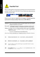
English Read Me First! When you installing AGP card, please make sure the following notice is fully understood and practiced. If your AGP card has "AGP 4X/8X (1.5V) notch" (show below), please make sure your AGP card is AGP 4X/8X. AGP 4 X/8 X notch Caution: AGP 2X card is not supported by VIA K8M800. You might experience system unable to boot up normally. Please insert an AGP 4X/8X card.
3. Hold components by the edges and try not touch the IC chips, leads or connectors, or other components. 4. Place components on a grounded antistatic pad or on the bag that came with the components whenever the components are separated from the system. 5. Ensure that the ATX power supply is switched off before you plug in or remove the ATX power connector on the motherboard. Installing the motherboard to the chassis...
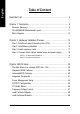
English Table of Content Read Me First! .................................................................................... 4 Chapter 1 Introduction ........................................................................ 8 Features Summary ......................................................................................... 8 GA-K8VM800M Motherboard Layout .......................................................... 11 Block Diagram ......................................................................
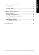
Save & Exit Setup .......................................................................................... 50 Exit Without Saving ....................................................................................... 50 Chapter 4 Technical Reference ......................................................... 53 @BIOS™ Introduction .................................................................................. 53 Flash BIOS Method Introduction ............................................................
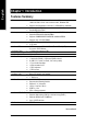
English Chapter 1 Introduction Features Summary CPU Chipset Mem ory Slots On-Board IDE — — — — — — — — — — — On-Board Floppy — On-Board Serial ATA — On-Board Peripherals — — — — — — — On-Board VGA — On-Board LAN — — On-Board Sound — — — — — — On-Board SATA RAID — — — — I/O Control — Socket 754 for AMD AlthlonTM 64 processor (K8) 128K L1& 256K / 512K / 1M L2 cache on die , 800MHz FSB Support core frequencies in excess of 1.
BIOS Additional Features Overclocking Form Factor — — — — — — — — — — — CPU/System fan revolution detect CPU temperature detect System voltage detect CPU/System fan fail warning Licensed AWARD BIOS Supports Q-Flash Supports Thermal Shutdown function Supports @BIOS Supports EasyTune Over Clock (CPU/DDR/AGP/PCI) by BIOS Micro ATX size form factor 24.4cm x 24.
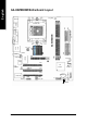
CPU_FAN MS / KB VGA LPT FDD GA-K8VM800M RAM_LED COMA ATX R_USB SOC KET 754 VIA K8M 800 IDE2 F_AU DIO BIOS DDR1 AGP IT8705F SU R_C EN DDR2 AUDIO IDE1 A TX_12V LAN USB SYS_FAN SATA1 PCI1 VIA CODEC IR CD_I N PCI2 V T8 237 SATA0 PCI3 BATTERY RTL8 100C GAME SPDI F_IO COMB F_U SB1F_U SB2 INFO_LINK F_PANEL English GA-K8VM800M Motherboard Layout PWR_LE D CLR_CMOS CI GA-K8VM800M Motherboard - 10 -
English Block Diagram AMD AlthlonTM 64 processor (K8) AGP 4X/8X AGPCLK (66MHz) VGA Port CPUCLK+/- (200M Hz) H.T. Bus 800MHz DDR RAM 400/333/266/200MHz VIA K8M800 LAN RJ45 3 PCI 33 MHz 14.
English GA-K8VM800M Motherboard - 12 -
English Chapter 2 Hardware Installation Process To set up your computer, you must complete the following steps: Step 1 - Install the Central Processing Unit (CPU) Step 2 - Install memory modules Step 3 - Install expansion cards Step 4 - Install I/O Peripherals Cables Step 4 Step 1 Step 2 Step 4 Step 4 Step 3 Congratulations! You have accomplished the hardware installation! Turn on the power supply or connect the power cable to the power outlet. Continue with the BIOS/software installation.
English Step 1: Install the Central Processing Unit (CPU) Before installing the processor and cooling fan, adhere to the following warning: 1. Please make sure the CPU type is supported by the motherboard. 2. The processor will overheat without the heatsink and/or fan, resulting in permanent irreparabledamage. 3. If you do not match the CPU socket Pin 1 and CPU cut edge well, it will cause improper installation. Please change the insert orientation. 4.
Figure 3. Application of thermal grease to the processor. Step 1-3.Once the thermal grease has been applied to the processor, the heatsink can be attached to the processor. Align the heatsink assembly with the support frame m ating with the backer plate standoffs as shown in Figure 4 & 5. Figure 4 & 5. Alignm ent of heatsink assembly with standoffs. Step 1-4. Connect the fan power wires to the header on the m otherboard as shown in Figure 6. Figure 6. Connecting the fan power wires.
English Step 2: Install Memory Modules Before installing the memory modules, adhere to the following warning: 1. When RAM_LED is ON, do not install / remove DIMM from socket. 2. Please note that the DIMM module can only fit in one direction due to the one notch. Wrong orientation will cause improper installation. Please change the insert orientation. The motherboard has 2 dual inline memory module (DIMM) sockets. The BIOS will automatically detects memory type and size.
1. Read the related expansion card's instruction document before install the expansion card into the computer. 2. Remove your computer's chassis cover, screws and slot bracket from the computer. 3. Press the expansion card firmly into expansion slot in motherboard. 4. Be sure the metal contacts on the card are indeed seated in the slot. 5. Replace the screw to secure the slot bracket of the expansion card. 6. Replace your computer's chassis cover. 7.
English Step 4: Install I/O Peripherals Cables Step 4-1: I/O Back Panel Introduction PS/2 Keyboard and PS/2 Mouse Connector PS/2 Mouse Connector (6 pin Female) This connector supports standard PS/2 keyboard and PS/2 mouse. PS/2 Keyboard Connector (6 pin Female) / USB/LAN Connector LAN USB 0 USB 2 USB 1 USB 3 GA-K8VM800M Motherboard - 18 - Before you connect your device(s) into USB connector(s), please make sure your device (s) such as USB keyboard,mouse, scanner, zip, speaker...etc.
Parallel Port (25 pin Female) COMA Serial Port (9 pin Male) This connector supports 1 standard COM port, 1 Parallel port and 1 VGA port. Device like printer can be connected to Parallel port; mouse and modem etc can be connected to Serialports. VGA VGA Port (15 pin Female) After install onboard audio driver, you may connect speaker to Line Out jack, microphone to MIC In jack. Device like CD-ROM,walkman etc. can be connected to Line-In jack.
English Step 4-2: Connectors Introduction 1 3 2 5 10 6 11 12 4 7 14 16 22 8 21 13 17 1) ATX_12V 2) ATX (Power Connector) 3) CPU_FAN 4) 5) 6) 7) 8) 9) 10) 11) SYS_FAN FDD IDE1 / IDE2 SATA0 / SATA1 F_PANEL PWR_LED RAM_LED F_AUDIO GA-K8VM800M Motherboard 15 18 19 20 9 12) SUR_CEN 13) SPDIF_IO 14) CD_IN 15) 16) 17) 18) 19) 20) 21) 22) - 20 - F_USB1 / F_USB2 IR GAME INFO_LINK COMB CLR_CMOS CI BAT
English 1) ATX_12V (+12V Power Connector) This connector (ATX_12V) supplies the CPU operation voltage (Vcore). If this "ATX_12V connector" is not connected, system cannot boot. 4 2 3 1 Pin No. 1 2 3 4 Definition GND GND +12V +12V 2) ATX (ATX Power Connector) AC power cord should only be connected to your power supply unit after ATX power cable and other related devices are firmly connected to the motherboard. Pin No. 1 2 3 11 20 - 21 - 1 10 Definition 3.3V 3.
English 3) CPU_FAN (CPU Fan Connector) Please note, a proper installation of the CPU cooler is essential to prevent the CPU from running under abnormal condition or damaged by overheating. The CPU fan connector supports Max. current up to 600 m A. Pin No. 1 2 3 1 Definition GND +12V Sense 4) SYS_FAN (System Fan Connector) This connector allows you to link with the cooling fan on the system case to lower the system temperature. 1 GA-K8VM800M Motherboard - 22 - Pin No.
Please connect the floppy drive ribbon cables to FDD. It supports 360K, 1.2M, 720K, 1.44M and 2.88M bytes floppy disk types. The red stripe of the ribbon cable must be the sam e side with the Pin1. 34 33 2 1 6) IDE1 / IDE2 (IDE1 / IDE2 Connector) Im portant Notice: Please connect first hard disk to IDE1 and connect CD-ROM to IDE2. The red stripe of the ribbon cable must be the sam e side with the Pin1.
English 7) SATA0 / SATA1 (Serial ATA Connector) You can connect the Serial ATA device to this connector. If you wish to use RAID function, please use it in unity with BIOS and install the correct driver to have proper operation. 1 7 Pin No. 1 2 3 4 5 6 7 Definition GND TXP TXN GND RXN RXP GND 8) PWR_LED PWR_LED is connect with the system power indicator to indicate whether the system is on/off. It will blink when the system enters suspend mode.
Please connect the power LED, PC speaker, reset switch and power switch etc. of your chassis front panel to the F_PANEL connector according to the pin assignment below.
_ Do not remove memory modules while RAM _LED is on. It might cause short or other unexpected damages due to the stand by voltage. Remove memory modules only when AC power cord is disconnected. + English 10) RAM_LED 11) F_AUDIO (Front Audio Connector) If you want to use Front Audio connector, you must rem ove 5-6, 9-10 Jumper. In order to utilize the front audio header, your chassis must have front audio connector.
English 12) SUR_CEN (Surround Center Connector) Please contact your nearest dealer for optional SUR_CEN cable. 1 5 2 6 Pin No. 1 2 3 4 5 6 Definition SUROUTL SUROUTR GND No Pin CENTER_OUT BASS_OUT 13) SPDIF_IO (SPDIF In / Out Connector) The SPDIF output is capable of providing digital audio to external speakers or com pressed AC3 data to an external Dolby Digital Decoder. Use this feature only when your stereo system has digital input function. Be careful with the polarity of the SPDIF_IO connector.
English 14) CD_IN (CD In Connector) Connect CD-ROM or DVD-ROM audio out to the connector. 1 Pin No. 1 2 3 4 Definition CD-L GND GND CD-R 15) F_USB1 / F_USB2 (Front USB Connector) Be careful with the polarity of the front USB connector. Check the pin assignment carefully while you connect the front USB cable, incorrect connection between the cable and connector will m ake the device unable to work or even damage it. For optional front USB cable, please contact your local dealer.
Make sure the pin 1 on the IR device is aling with pin one the connector. To enable the IR function on the board, you are required to purchase an option IR module. Be careful with the polarity of the IR/CIR or IR connector. Check the pin assignm ent carefully while you connect the IR cable, incorrect connection between the cable and connector will make the device unable to work or even damage it. For optional IR cable, please contact your local dealer. Pin No.
English 18) INFO_LINK This connector allows you to connect some external devices to provide you extra function. Check the pin assignm ent while you connect the external device cable. Please contact your nearest dealer for optional external device cable. 2 10 1 9 Pin No. 1 2 3 4 5 6 7 8 9 10 Definition SMBCLK VCC SMBDATA GPIO GND GND No Pin NC +12V +12V 19) COMB (COM B Connector) Be careful with the polarity of the COMB connector.
You m ay clear the CMOS data to its default values by this jumper. To clear CMOS, temporarily short 1-2 pin. Default doesn't include the "Shunter" to prevent from improper use this jumper. 1 Open: Normal 1 Short: Clear CMOS 21) CI (Chassis Intrusion, Case Open) This 2-pin connector allows your system to enable or disable the "case open" item in BIOS if the system case begin rem ove. 1 - 31 - Pin No.
English 22) BATTERY + CAUTION Danger of explosion if battery is incorrectly replaced. Replace only with the sam e or equivalent type recommended by the manufacturer. Dispose of used batteries according to the manufacturer's instructions. If you want to erase CMOS... 1. Turn OFF the computer and unplug the power cord. 2. Rem ove the battery, wait for 30 second. 3. Re-install the battery. 4. Plug the power cord and turn ON the computer.
English - 33 - Hardware Installation Process
English GA-K8VM800M Motherboard - 34 -
BIOS Setup is an overview of the BIOS Setup Program. The program that allows users to modify the basic system configuration. This type of information is stored in battery-backed CMOS RAM so that it retains the Setup information when the power is turned off. ENTERING SETUP Powering ON the computer and pressing immediately will allow you to enter Setup. If you require more advanced B IO S settings, please go to " Adv anced BI O S" setting menu.
English Main Menu The on-line description of the highlighted setup function is displayed at the bottom of the screen. Status Page Setup Menu / Option Page Setup Menu Press F1 to pop up a small help window that describes the appropriate keys to use and the possible selections for the highlighted item. To exit the Help Window press . The Main Menu (For example: BIOS Ver. : D8) Once you enter Award BIOS CMOS Setup Utility, the Main Menu (as figure below) will appear on the screen.
English l PC Health Status This setup page is the System auto detect Temperature, voltage, fan, speed. l Frequency/Voltage Control This setup page is control CPU’s clock and frequency ratio. l Load Fail-Safe Defaults Fail-Safe Defaults indicates the value of the system parameters which the system would be in safe configuration. l Load Optimized Defaults Optimized Defaults indicates the value of the system parameters which the sy stem would be in best performance configuration.
English Standard CMOS Features CMOS Setup Utility -Co py right (C) 1984 -2004 Aw ard Software Stan dard CM OS Features } } } } Date (mm:dd :y y ) Time (hh:mm :ss) Tue, Jan 2 7 2004 22:3 1:24 IDE P rimary M aster IDE P rimary Slave IDE Secondary M aster IDE Secondary Slave [No ne] [No ne] [No ne] [No ne] Driv e A Driv e B Flopp y 3 Mode Suport [1.44M, 3.
The category identifies the ty pes of floppy disk driv e A or driv e B that has been installed in the computer. None No floppy driv e installed 360K, 5.25" 5.25 inch PC-ty pe standard driv e; 360K by te capacity . 1.2M, 5.25" 5.25 inch AT-ty pe high-density driv e; 1.2M by te capacity (3.5 inch w hen 3 Mode is Enabled). 720K, 3.5" 3.5 inch double-sided driv e; 720K by te capacity 1.44M, 3.5" 3.5 inch double-sided driv e; 1.44M by te capacity . 2.88M, 3.5" 3.5 inch double-sided driv e; 2.88M by te capacity .
English Advanced BIOS Features CMOS Setup Utility -Co py right (C) 1984 -2004 Aw ard Software Advanced BI OS Features Firs t Boot D evice Seco nd Boot D evice Thir d Boot D evice Pas sword Check [Flo ppy ] [HDD -0] [CDROM] [Setup] Item Help Menu L evel} Selec t Boot D evice prio rity [Flo ppy ] Boot from floppy [LS1 20] Boot from L S120 [HDD -0] Boot from Firs t HDD [HDD -1] Boot from Secon d HDD higf: M ove Enter: Select F5: P revious Values +/-/PU/PD: Value F6: Fa il-Save De fault F10: Save ESC: Exi
CMOS Setup Utility -Co py right (C) 1984 -2004 Aw ard Software Inte grated Periphe rals IDE DMA tran sfer ac cess On-Chip IDE Chan nel 0 On-Chip IDE Chan nel 1 OnChip Serial ATA AC97 Audio USB 1 .1 Contr oller USB 2 .
English OnChi p Serial ATA Enabled Disabled Enable VT8237 Serial ATA supported. (Default v alue) Disable VT8237 Serial ATA supported. AC97 Audio Auto Disabled Enable onboard AC'97 audio function. (Default v alue) Disable this function. USB 1.1 Controller Disable USB 1. 1 host controller if y ou are not using USB dev ices. Enabled Enable USB 1. 1 controller. (Default v alue) Disabled Disable USB 1. 1 controller. USB 2.0 Controller Disable USB 2.
Auto 3F8/ IRQ4 2F8/ IRQ3 3E8/ IRQ4 2E8/ IRQ3 Disabled English Onboard Serial P ort 2 BIOS w ill autom atically s etup the port 2 address. Enable onboard Serial port 2 and address is 3F8. Enable onboard Serial port 2 and address is 2F8. (Default v alue) Enable onboard Serial port 2 and address is 3E8. Enable onboard Serial port 2 and address is 2E8. Disable onboard Serial port 2. UART Mode Select This item allow s Normal IrDA ASKIR y ou to determine w hich infrared(IR) function of onboard I/O chip.
English Power Management Setup CMOS Setup Utility -Co py right (C) 1984 -2004 Aw ard Software Powe r Manag ement Setup ACPI Suspend Ty pe x USB D evice Wa ke-Up Fr om S3 Soft- Off by P WRBTN AC Back Func tion Key bo ard Powe r On Mous e Powe r On PME E vent Wake Up Modem Ring Re sume Resu me by A larm x Date ( of Month) Alarm x Time ( hh:mm:ss) Alarm higf: M ove Enter: Select F5: P revious Values [S1(P OS)] Disa bled [Instan t-Off] [Soft-Off] [Disa bled] [Disa bled] [Enab led] [Enab led] [Disa bled] Ever
English Modem Ring On An incoming call v ia m odem can aw ake the sy stem from any suspend s tate. Disabled Disable Modem Ring on func tion. Enabled Enable Modem R ing on function. (Default v alue) Resume by Alarm You c an set "R esume by Alarm" item at "Enabled" and key in data/time to pow er on sy stem. Disabled Disable this function. (Default v alue) Enabled Enable alarm function to POWER ON sy stem. If RTC Alarm Lead To Pow er On is Enabled.
English PC Health Status CMOS Setup Utility -Co py right (C) 1984 -2004 Aw ard Software PC H ealth Status Rese t Case Open Status Case O pened Vcore DDR25V +3.
CMOS Setup Utility -Co py right (C) 1984 -2004 Aw ard Software Frequ ency /Voltage Con trol CPU Host Clock Con trol x CPU H ost Freq uency PCI/A GP Frequ ency [Disa bled] 200 33/66 higf: M ove Enter: Select F5: P revious Values +/-/PU/PD: Value F6: Fa il-Save De fault Item Help Menu L evel} F10: Save ESC: Exit F7: Optimized Defa ults F1: General Help Incorrect using these features may cause y our sy stem broken.
English Load Fail-Safe Defaults CMOS Setup Utility -Co py right (C) 1984 -2004 Aw ard Software } } } } } } } Stan dard CM OS Features Advanced BI OS Features Inte grated Periphe rals Powe r Manag ement Setup PnP/PCI Con figurations PC H ealth Status Frequ ency /Voltage Con trol Load Fail-Sa fe Defa ults Load Optimized Defa ults Set Supervis or Pass word Set U ser Pass word Load Fail-Sa fe Defau ltsSave (Y/N& )? Exit N Setup Exit Without Saving higf: Selec t Item F10: Save & Exit Setup ESC: Quit F8: Q- F
English Set Supervisor/User Password CMOS Setup Utility -Co py right (C) 1984 -2004 Aw ard Software } } } } } } } Stan dard CM OS Features Advanced BI OS Features Inte grated Periphe rals Powe r Manag ement Setup Ente r Passw ord: PnP/PCI Con figurations Load Fail-Sa fe Defa ults Load Optimized Defa ults Set Supervis or Pass word Set U ser Pass word Save & Exit Setup Exit Without Saving PC H ealth Status Frequ ency /Voltage Con trol ESC: Quit F8: Q- Flash higf: Selec t Item F10: Save & Exit Setup Chan
English Save & Exit Setup CMOS Setup Utility -Co py right (C) 1984 -2004 Aw ard Software } } } } } } } Stan dard CM OS Features Advanced BI OS Features Inte grated Periphe rals Powe r Manag ement Setup PnP/PCI Con figurations PC H ealth Status Frequ ency /Voltage Con trol Load Fail-Sa fe Defa ults Load Optimized Defa ults Set Supervis or Pass word Set U ser Pass word Save to CMOS an d EXITSave (Y/N)? Y Setup & Exit Exit Without Saving higf: Selec t Item F10: Save & Exit Setup ESC: Quit F8: Q- Flash Sav
English - 51 - BIOS Setup
English GA-K8VM800M Motherboard - 52 -
English Chapter 4 Technical Reference @BIOS™ Introduction Gigabyte announces @BIOS Windows BIOS Live Update Utility Have you ever updated BIOS by yourself? Or like many other people, you just know what BIOS is, but always hesitate to update it? Because you think updating newest BIOS is unnecessary and actually you don't know how to update it. Maybe not like others, you are very experienced in BIOS updating and spend quite a lot of time to do it. But of course you don't like to do it too much.
English Flash BIOS Method Introduction Method 1 : Q-Flash Utility TM TM Q-Flash is a BIOS flash utility embedded in Flash ROM. With this utility, users only have to stay in the BIOS menu when they want to update BIOS. Q-Flash™ allows users to flash BIOS without any utility in DOS or Windows. Using QTM Flash indicating no more fooling around with any complicated instructions and operating system since it is in the BIOS menu.
TM Updating BIOS with Q-Flash Utility on Dual BIOS Motherboards. Some of Gigabyte motherboards are equipped with dual BIOS. In the BIOS menu of the motherboards supporting Q-Flash and Dual BIOS, the Q-Flash utility and Dual BIOS utility are combined in the same screen. This section only deals with how to use Q-Flash utility. In the following sections, we take GA-8KNXP Ultra as the example to guide you how to flash BIOS from an older version to the latest version. For example, from Fa3 to Fba.
Exploring the Q-Flash / Dual BIOS utility screen English TM The Q-Flash / Dual BIOS utility screen consists of the following key components. Dual BIOS Utility Boot From......................................... Main Bios Main ROM Type/Size............................ SST 49LF003A Backup ROM Type/Size........................
In this example, we only download one BIOS file to the floppy disk so only one BIOS file, 8KNXPU.Fba, is listed. Please confirm again you have the correct BIOS file for your motherboard. Dual BIOS Utility Boot From......................................... Main Bios Main ROM Type/Size............................SST 49LF003A Backup ROM Type/Size........................
English 4. Press any keys to return to the Q-Flash menu when the BIOS updating procedure is completed. Dual BIOS Utility Boot From......................................... Main Bios Main ROM Type/Size............................ SST 49LF003A Backup ROM Type/Size........................
CMOS Setup Utility-Copyright (C) 1984-2003 Award Software } } Standard CMOS Features Advanced BIOS Features Top Performance Load Fail-Safe Defaults } } Integrated Peripherals Power Management Setup Load Optimized Defaults Set Supervisor Password } } PnP/PCI Configurations PC Health Status Set User Password Save & Exit Setup } Frequency/Voltage Control Exit Without Saving Press Enter on your keyboard higf: Select Item F10: Save & Exit Setup ESC: Quit F8: Dual BIOS/Q-Flash CMOS Setup Utility-Co
English Part Two: TM Updating BIOS with Q-Flash Utility on Single-BIOS Motherboards. This part guides users of single-BIOS motherboards how to update BIOS using the Q-Flash™ utility. TM Entering the Q-Flash utility: Step1: To use the Q-Flash utility, you must press Del in the boot screen to enter BIOS menu.
TM Steps: 1. Press arrow buttons on your keyboard to move the light bar to "Update BIOS from Floppy" item in the Q-Flash menu and press Enter button. Later, you will see a box pop up showing the BIOS files you previously downloaded to the floppy disk. If you want to save the current BIOS for backup purpose, you can begin Step 1 with "Save BIOS to Floppy" item. 2. Move to the BIOS file you want to flash and press Enter.
English 3. Press Y button on your keyboard after you are sure to update BIOS. Then it will begin to update BIOS. The progress of updating BIOS will be shown at the same time. Q-Flash Utility V1.30 Flash Type/Size.............................. SST 49LF003A 256K The porcess of updating BIOS Keep DMI Data Enable Updating BIOS Update BIOS fromNow... Floppy >>>>>>>>>>>>>>........................
If you don't have DOS boot disk, we recommend that you used Gigabyte @BIOS™ program to flash BIOS. Press here. 2. Click Start/ Programs/ GIGABYTE/ @BIOS. 1. Click "@BIOS" item. (1) 3.Click "P" (2) Click here 4. Please select @BIOS sever site, then Click "OK". (4) (3) Methods and steps: 1. Update BIOS through Internet: a. Click "Internet Update" icon b. Click "Update New BIOS" icon c . Select @BIOS™ sever d. Select the exact model name on your motherboard e.
English 3. Save BIOS In the very beginning, there is "Save Current BIOS" icon shown in dialog box. It means to save the current BIOS version. 4. Check out supported motherboard and Flash ROM: In the very beginning, there is "About this program" icon shown in dialog box. It can help you check out which kind of motherboard and which brand of Flash ROM are supported. Note: a. In method I, if it shows two or more motherboard's model names to be selected, please make sure your motherboard's model name again.
The installation of windows 98SE/2K/ME/XP is very simple. Please follow next step to install the function! Stereo Speakers Connection and Settings: We recommend that you use the speaker with amplifier to acqiire the best sound effect if the stereo output is applied. STEP 1: Connect the stereo speakers or earphone to "Line Out". Line Out STEP 2 : After installation of the audio driver, you'll find an icon on the taskbar's status area.
English 4 Channel Analog Audio Output Mode STEP 1 : Connect the front channels to "Line Out", the rear channels to "Line In". Line Out STEP 2 : After installation of the audio driver, you'll find an icon on the taskbar's status area. Click the audio icon "Sound Effect" from the windows tray at the bottom of the screen. STEP 3 : Select "Speaker Configuration", and choose the "4 channel for 4 speakers out put". Disable "Only SURROUND-KIT", and press "OK".
English Basic 6 Channel Analog Audio Output Mode Use the back audio panel to connect the audio output without any additional module. STEP 1 : Connect the front channels to "Line Out",the rear Line In channels to "Line In", and the Center/Subwoofer channels to "MIC In". MIC In Line Out STEP 2 : After installation of the audio driver, you'll find an icon on the taskbar's status area. Click the audio icon "Sound Effect" from the windows tray at the bottom of the screen.
English Advanced 6 Channel Analog Audio Output Mode (using Audio Combo Kit,Optional Device): (Audio Combo Kit provides SPDIF output port : optical & coaxis and SURROUND-KIT : Rear R/L & CEN /Subwoofer) SURROUND-KIT access analog output to rear channels and Center/Subwoofer channels. It is the best solution if you need 6 channel output, Line In and MIC at the same time. "SURROUND-KIT" is included in the GIGABYTE unique "Audio Combo Kit" as picture.
English STEP 3 : Connect the front channels to back audio panel's "Line Out", the rear channels to SURROUND-KIT's REAR R/L, and the Center/Subwoofer channels to SURROUND-KIT's SUB CENTER. STEP 4 : Click the audio icon "Sound Effect" from the windows tray at the bottom of the screen. STEP 5 : Select "Speaker Configuration", and choose the "6 channel for 5.1 speakers out put". Enable "Only SURROUND-KIT" and press "OK".
English SPDIF Output Device (Optional Device) A "SPDIF output" device is available on the motherboard. Cable with rear bracket is provided and could link to the "SPDIF output" connector (As picture.) For the further linkage to decoder, rear bracket provides coaxial cable and Fiber connecting port. 1. Connect the SPDIF output device to the rear bracket of PC, and fix it with screw. 2. Connect SPDIF device to the motherboard. 3. Connect SPDIF to the SPDIF decoder.
Jack-Sensing provides audio connectors error-detection function. Install Microsoft DirectX8.1 before to enable Jack-Sensing support for Windows 98/98SE/2000 /ME. Jack-Sensing includes 2 parts: AUTO and MANUAL. Following is an example for 2 channels (Windows XP): Introduction of audio connectors You may connect CDROM, Walkman or others audio input devices to Line In jack, speakers, earphone or others output devices to Line Out jack, and microphone to MIC In jack.
English If you set wrong with the connectors, the warning message will come out as right picture. Manual setting: If the device picture shows different from what you set, please press "Manual Selecion" to set.
What is Xpress Recovery ? Xpress Recovery is a utility used to back up and restore an OS partition. If the hard drive is not working properly, the user can restore the drive to its original state. 1. Supports FAT16, FAT32, and NTFS formats 2. Must be connected to the IDE1 Master 3. Allows installation of only one OS 4. Must be used with an IDE hard disk supporting HPA 5. The first partition must be set as the boot partition. When the boot partition is backed up, please do not alter its size. 6.
English 2. Press F9 during powering on the computer. (Text Mode) Press F9 during powering on the computer. Award Modular BIOS v6.00PG, An Energy Star Al ly Copyright (C) 1984-2002, Award Software, Inc. Intel 865PE AGPSetBIOS for 8IPE1000MT F1 Check SystemHealth OK . . . F9 For Xpress Recovery PressDEL to enter SETUP / Q-Flash, F9 ForXpress Recovery 08/16/2002-I845GE-6A69YG01C-00 Xpress Recovery V1.0 (C) Copy Right 2003. GIGABYTE Technology CO. , Ltd. 1. Execute Backup Utility 2.
The backup utility will automatically scan your system and back up data as a backup image in your hard drive. Not all systems support access to Xpress Recovery by pressing the F9 key during computer power on. If this is the case, please use the boot from CD-ROM method to enter Xpress Recovery. 2. Execute Restore Utility: ! This program will recover your system to factory default. Press R to restore your system back to factory default or press Esc to exit Restores backup image to original state. 3.
English Serial ATA BIOS Setting Utility Introduction RAID Levels RAID (Redundant Array of Independent Disks) is a method of com bining two hard disk drives into one logical unit. The advantage of an Array is to provide better performance or data fault tolerance. Fault tolerance is achieved through data redundant operation, where if one drives fails, a mirrored copy of the data can be found on another drive. This can prevent data loss if the operating system fails or hangs.
1) Have ready your hard drives for RAID construction. Note: To achieve best performance, it is recommended that the hard drives used are of similar make and storage capacity. 2) Please attach the hard drive connectors to their appropriate location on the motherboard ie. IDE, SCSI, or SATA. 3) Enter the motherboard BIOS and locate RAID setup (Please refer to the section on Integrated Peripherals). 4) Enter RAID setup in the BIOS and select the RAID type (For instance, enter to select VIA RAID).
English Create Disk Array 1. Use the arrow keys to navigate the main m enu. Use the up and down arrow keys to select the Create Array com mand and press to call out the list of creation steps. VIA Technologies,Inc. VIA VT8237 Serial ATA BIOS Setting Utility V1.
VIA Technologies,Inc. VIA VT8237 Serial ATA BIOS Setting Utility V1.20 u Auto Setup For Performance Create a RAID array with the hard disks u Array Mode RAID 0 (Striping) attached to VIA IDE controller u Select Disk Drives F1 : View Array/disk Status u Block Size 64K h,i : Move to next item u Start Create Process Enter : Confirm the selection ESC : Exit Mode Size(GB) [*]Serial_Ch0 Master Channel Driver Name ST380013AS Array Name SATA 74.
English Delete Disk Array A RAID can be deleted after it has been created. To delete a RAID, use the following steps: 1. Select Delete Array in the main m enu and press . The channel colum n will be activated. 2. Select the member of an array that is to be deleted and press . A warning m essage will show up, press Y to delete or press N to cancel. VIA Technologies,Inc. VIA VT8237 Serial ATA BIOS Setting Utility V1.
View Array Status Press the F1 key to show the array status on the lower screen. If there are no disk arrays then nothing will be displayed on the screen. VIA Technologies,Inc. VIA VT8237 Serial ATA BIOS Setting Utility V1.
English C. Installing the RAID drivers For the Windows operating system (Win NT, WinXP, Win2000 ), for IDE RAID/SCSI/Serial ATA functioning, the driver m ust first be transferred to a floppy disk. Please follow the steps below to com plete driver transfer to a floppy disk: 1) Please insert the provided driver CD into the hard disk drive eg. Drive D: 2) Insert a blank formatted floppy disk into the floppy disk drive. 3) Either from "Com mand Prompt" or DOS, please type in "D:\BootDrv\menu.exe"(Refer to Fig.
English Revision ChapterHistory 5 Appendix Install Drivers Pictures below are shown in Windows XP Insert the driver CD-title that came with your motherboard into your CD-ROM drive, the driver CD-title will auto start and show the installation guide. If not, please double click the CD-ROM device icon in "My computer", and execute the setup.exe. INSTALL CHIPSET DRIVER This page shows the drivers that need to be installed for the system.
English Driver installation finished ! You have to reboot system ! Item Description n VIA 4IN1Driver VIA Chipset Driver n VIA K8M800 VGA Driver VIA VGA Driver n USB Patch for WinXP This patch driver can help you to resolve the USB device wake up S3 hang up issue in XP. n Realtek Lan Driver RealTek 10/100 LAN driver n RealTek AC97 Codec Driver Realtek Audio Driver n VIA 8237 Serial ATA Driver For VIA 8237 SATA Driver n VIA USB 2.0 Controller VIA USB 2.
This page reveals the value-added software developed by Gigabyte and its worldwide partners.
English SOFTWARE INFORMATION This page list the contects of softwares and drivers in this CD title. HARDWARE INFORMATION This page lists all device you have for this motherboard. CONTACT US Please see the last page for details.
Below is a collection of general asked questions. To check general asked questions based on a specific motherboard model, please log on to http://tw.giga-byte.com/faq/faq.htm Question 1: I cannot see some options that were included in previous BIOS after updating BIOS. Why? Answer: Some advanced options are hidden in new BIOS version. Please press Ctrl and F1 keys after entering BIOS menu and you will be able to see these options.
English Question 8: How do I disable onboard VGA card in order to add an external VGA card? Answer: Gigabyte motherboards will auto-detect the external VGA card after it is plugged in, so you don't need to change any setting manually to disable the onboard VGA. Question 9: Why cannot I use the IDE 2? Answer: Please refer to the user manual and check whether you have connected any cable that is not provided with the motherboard package to the USB Over Current pin in the Front USB Panel.
If you encounter any trouble during boot up, please follow the troubleshooting procedures. START Turn off the power and unplug the AC power cable, then remove all of the add-on cards and cables from motherboard. Please make sure motherboard & chassis are not short ? Yes Please isolate the short pin. No Failure has been excluded. Please make sure all jumper settings (such as CPU system bus speed, frequency ratio, voltage and etc) are set properly. Yes No Make sure the jumper setting are correct.
English A Is memory LED on and CPU fan running? No The problem could be caused by power supply, CPU, memory or CPU/memory socket itself. Yes Failure has been excluded. No Check if there is display. Yes Perhaps your VGA card / VGA slot or monitor is defective. Failure has been excluded. Turn off the system. Reboot after keyboard and mouse have been plugged in. Check if keyboard is working properly. No It is possible that your keyboard or keyboard connector is defective.
Customer/Country: Contact Person: Company: Phone No.: E-mail Add. : Model name/Lot Number: BIOS version: Hardware English & Technical Support/RMA Sheet PCB revision: O.S./A.S.: Mfs.
English Acronyms Acronyms Meaning ACPI Advanced Configuration and Power Interface APM Advanced Power Management AGP Accelerated Graphics Port AMR Audio Modem Riser ACR Advanced Communications Riser BIOS Basic Input / Output System CPU Central Processing Unit CMOS Complementary Metal Oxide Semiconductor CRIMM Continuity RIMM CNR Communication and Networking Riser DMA Direct Memory Access DMI Desktop Management Interface DIMM Dual Inline Memory Module DRM Dual Retention Mechanism
Meaning IOAPIC Input Output Advanced Programmable Input Controller ISA Industry Standard Architecture LAN Local Area Network I/O Input / Output LBA Logical Block Addressing LED Light Emitting Diode MHz Megahertz MIDI Musical Instrument Digital Interface MTH Memory Translator Hub MPT Memory Protocol Translator NIC Network Interface Card OS Operating System OEM Original Equipment Manufacturer PAC PCI A.G.P.
English GA-K8VM800M Motherboard - 94 -
English - 95 - Memo
English CONTACT US Contact us via the information in this page all over the world. — Taiwan Gigabyte Technology Co., Ltd. Address: No.6, Bau Chiang Road, Hsin-Tien, Taipei Hsien, Taiwan, R.O.C. Tel: 886 (2) 8912-4888 Fax: 886 (2) 8912-4003 Tech. Support: http://tw.giga-byte.com/TechSupport/ServiceCenter.htm Non-Tech. Support (Sales/Marketing issues): http://ggts.gigabyte.com.tw/nontech.asp Website: http://www.gigabyte.com.tw — USA G.B.T. INC. Address: 17358 Railroad St, City of Industry, CA 91748.