GA-M68MT-D3P GA-M68MT-S2P User's Manual Rev.
Motherboard GA-M68MT-D3P/GA-M68MT-S2P Dec. 31, 2010 Motherboard GA-M68MT-D3P GA-M68MT-S2P Dec.
Copyright © 2011 GIGA-BYTE TECHNOLOGY CO., LTD. All rights reserved. The trademarks mentioned in this manual are legally registered to their respective owners. Disclaimer Information in this manual is protected by copyright laws and is the property of GIGABYTE. Changes to the specifications and features in this manual may be made by GIGABYTE without prior notice.
Table of Contents GA-M68MT-D3P/GA-M68MT-S2P Motherboard Layout..................................................5 GA-M68MT-D3P/GA-M68MT-S2P Motherboard Block Diagram......................................6 Chapter 1 Hardware Installation......................................................................................7 1-1 1-2 1-3 Installation Precautions..................................................................................... 7 Product Specifications.........................................
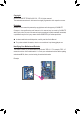
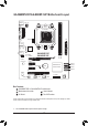
GA-M68MT-D3P/GA-M68MT-S2P Motherboard Layout KB_MS COMA ATX_12V Socket AM3+ VGA LPT ATX CPU_FAN F_AUDIO B_BIOS PCIEX16 Realtek RTL8211CL PCIEX1_1 PCIEX1_2 CODEC GA-M68MT-D3P GA-M68MT-S2P DDR3_1 M_BIOS AUDIO DDR3_2 iTE IT8720 LAN USB R_USB CLR_CMOS BAT SATA2_3 ® NVIDIA GeForce SATA2_2 7025/nForce 630a SATA2_1 SATA2_0 PCI F_PANEL SYS_FAN F_USB1 F_USB2 F_USB3 Box Contents GA-M68MT-D3P or GA-M68MT-S2P motherboard Motherboard driver disk User's Manual I/O Shield Two SATA cable
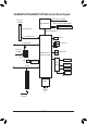
GA-M68MT-D3P/GA-M68MT-S2P Motherboard Block Diagram CPU CLK+/- (200 MHz) PCIe CLK (100 MHz) AM3+/AM3 CPU DDR3 1600/1333/1066/800 MHz Dual Channel Memory 1 PCI Express x16 Hyper Transport Bus PCI Express x16 1 D-Sub 10 USB 2.0/1.
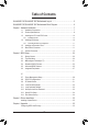
Chapter 1 1-1 Hardware Installation Installation Precautions The motherboard contains numerous delicate electronic circuits and components which can become damaged as a result of electrostatic discharge (ESD). Prior to installation, carefully read the user's manual and follow these procedures: • Prior to installation, do not remove or break motherboard S/N (Serial Number) sticker or warranty sticker provided by your dealer. These stickers are required for warranty validation.
1-2 Product Specifications CPU AM3+ Socket: - AMD AM3+ FX processors * You must install an external graphics card if you want to install Windows XP on your AM3+ CPU-based system. - AMD AM3 Phenom™ II processors/AMD Athlon™ II processors (Go to GIGABYTE's website for the latest CPU support list.) Hyper Transport 2000 MT/s Bus Chipset NVIDIA® GeForce 7025/nForce 630a Memory 2 x 1.
Back Panel Connectors 1 x PS/2 keyboard port 1 x PS/2 mouse port 1 x D-Sub port 1 x serial port 4 x USB 2.0/1.
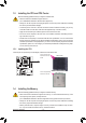
1-3 Installing the CPU and CPU Cooler Read the following guidelines before you begin to install the CPU: • Make sure that the motherboard supports the CPU. (Go to GIGABYTE's website for the latest CPU support list.) • Always turn off the computer and unplug the power cord from the power outlet before installing the CPU to prevent hardware damage. • Locate the pin one of the CPU. The CPU cannot be inserted if oriented incorrectly.
1-4-1 Dual Channel Memory Configuration DDR3_1 DDR3_2 This motherboard provides two DDR3 memory sockets and supports Dual Channel Technology. The two DDR3 memory sockets are divided into two channels and each channel has two memory sockets as following: Channel 0: DDR3_1 Channel 1: DDR3_2 Due to CPU limitation, read the following guidelines before installing the memory in Dual Channel mode. 1. Dual Channel mode cannot be enabled if only one DDR3 memory module is installed. 2.
D-Sub Port The D-Sub port supports a 15-pin D-Sub connector. Connect a monitor that supports D-Sub connection to this port. USB 2.0/1.1 Port The USB port supports the USB 2.0/1.1 specification. Use this port for USB devices such as a USB keyboard/mouse, USB printer, USB flash drive and etc. RJ-45 LAN Port The Gigabit Ethernet LAN port provides Internet connection at up to 1 Gbps data rate. The following describes the states of the LAN port LEDs.
1-7 Internal Connectors 1 3 5 2 9 11 6 10 4 1) 2) 3) 4) 5) ATX_12V ATX CPU_FAN SYS_FAN LPT 6) SATA2_0/1/2/3 7 8 7) 8) 9) 10) 11) 7 F_USB1/F_USB2/F_USB3 F_PANEL F_AUDIO CLR_CMOS BAT Read the following guidelines before connecting external devices: • First make sure your devices are compliant with the connectors you wish to connect. • Before installing the devices, be sure to turn off the devices and your computer. Unplug the power cord from the power outlet to prevent damage to the devices.
1/2) ATX_12V/ATX (2x2 12V Power Connector and 2x12 Main Power Connector) With the use of the power connector, the power supply can supply enough stable power to all the components on the motherboard. Before connecting the power connector, first make sure the power supply is turned off and all devices are properly installed. The power connector possesses a foolproof design. Connect the power supply cable to the power connector in the correct orientation.
3/4) CPU_FAN/SYS_FAN (Fan Headers) The motherboard has a 4-pin CPU fan header (CPU_FAN) and a 3-pin (SYS_FAN) system fan headers. Most fan headers possess a foolproof insertion design. When connecting a fan cable, be sure to connect it in the correct orientation (the black connector wire is the ground wire). The motherboard supports CPU fan speed control, which requires the use of a CPU fan with fan speed control design.
UG T DEBUG PORT DEBUG PORT DEBUG PORT DEBUG PORT 6) SATA2_0/1/2/3 (SATA 3Gb/s Connectors) The SATA connectors conform to SATA 3Gb/s standard and are compatible with SATA 1.5Gb/s standard. Each SATA connector supports a single SATA device. The NVIDIA® GeForce 7025/nForce 630a chipset supports RAID 0, RAID 1, RAID 5, RAID 10, and JBOD. Refer to Chapter 4, "Configuring SATA Hard Drive(s)," for instructions on configuring a RAID array. Pin No. 1 7 SATA2_3 1 7 SATA2_2 1 7 SATA2_1 G.
8) F_PANEL (Front Panel Header) Connect the power switch, reset switch, speaker, chassis intrusion switch/sensor and system status indicator on the chassis to this header according to the pin assignments below. Note the positive and negative pins before connecting the cables.
9) F_AUDIO (Front Panel Audio Header) The front panel audio header supports Intel High Definition audio (HD) and AC'97 audio. You may connect your chassis front panel audio module to this header. Make sure the wire assignments of the module connector match the pin assignments of the motherboard header. Incorrect connection between the module connector and the motherboard header will make the device unable to work or even damage it. 2 10 1 9 For HD Front Panel Audio: Pin No.
11) BAT (Battery) The battery provides power to keep the values (such as BIOS configurations, date, and time information) in the CMOS when the computer is turned off. Replace the battery when the battery voltage drops to a low level, or the CMOS values may not be accurate or may be lost. You may clear the CMOS values by removing the battery: 1. Turn off your computer and unplug the power cord. 2. Gently remove the battery from the battery holder and wait for one minute.
Chapter 2 BIOS Setup To access the BIOS Setup program, press the key during the POST when the power is turned on. To see more advanced BIOS Setup menu options, you can press + in the main menu of the BIOS Setup program. To upgrade the BIOS, use either the GIGABYTE Q-Flash or @BIOS utility. • Q-Flash allows the user to quickly and easily upgrade or back up BIOS without entering the operating system.
• If you do not find the settings you want in the Main Menu or a submenu, press + to access more advanced options. • When the system is not stable as usual, select the Load Optimized Defaults item to set your system to its defaults. • The BIOS Setup menus described in this chapter are for reference only and may differ by BIOS version. 2-3 MB Intelligent Tweaker(M.I.T.) CMOS Setup Utility-Copyright (C) 1984-2010 Award Software MB Intelligent Tweaker(M.I.T.
DRAM Configuration CMOS Setup Utility-Copyright (C) 1984-2010 Award Software DRAM Configuration x x x x x x x x x x x x DCTs Mode DDR3 Timing Items CAS# latency RAS to CAS R/W Delay Row Precharge Time Minimum RAS Active Time 1T/2T Command Timing TwTr Command Delay Trfc0 for DIMM1 Trfc1 for DIMM3 Write Recovery Time Precharge Time Row Cycle Time RAS to RAS Delay CKE Power Down Mode CKE Power Down Control Enter: Select : Move F5: Previous Values [Unganged] [Auto] Auto Auto
Precharge Time Options are: Auto (default), 4T~7T. Row Cycle Time Options are: Auto (default), 11T~42T. RAS to RAS Delay Options are: Auto (default), 4T~7T. CKE Power Down Mode Determines whether to set the memory to power down mode when the CKE pin is closed. (Default: Disabled) CKE Power Down Control Allows you to select a CKE power down mode. Options are per Channel (Default), per CS. DDR3 Voltage Control Allows you to set the memory voltage. Normal Supplies the memory voltage as required.
Date (mm:dd:yy) Sets the system date. Time (hh:mm:ss) Sets the system time. IDE Channel 0, 1, 2, 3 Master IDE HDD Auto-Detection, IDE Auto-Detection Press to autodetect the parameters of the SATA device on this channel. IDE Channel 0, 1 Master, Extended IDE Drive Configure your SATA devices by using one of the three methods below: • Auto Lets the BIOS automatically detect SATA devices during the POST.
2-5 Advanced BIOS Features CMOS Setup Utility-Copyright (C) 1984-2010 Award Software Advanced BIOS Features Virtualization AMD K8 Cool&Quiet control CPU Unlock (Note) CPU core Control CPU core 0 (Note) CPU core 1 (Note) CPU core 2 (Note) CPU core 3 (Note) Hard Disk Boot Priority First Boot Device Second Boot Device Third Boot Device Password Check HDD S.M.A.R.T.
First/Second/Third Boot Device Specifies the boot order from the available devices. Password Check Specifies whether a password is required every time the system boots, or only when you enter BIOS Setup. After configuring this item, set the password(s) under the Set Supervisor/User Password item in the BIOS Main Menu. Setup A password is only required for entering the BIOS Setup program. (Default) System A password is required for booting the system and for entering the BIOS Setup program.
2-6 Integrated Peripherals CMOS Setup Utility-Copyright (C) 1984-2010 Award Software Integrated Peripherals NV Serial-ATA Controller } Serial-ATA RAID Config Onboard Audio Function On-Chip MAC Lan Onboard LAN Boot ROM Onboard Serial Port 1 Onboard Parallel Port Parallel Port Mode x ECP Mode Use DMA USB Controllers USB Legacy Function USB Storage Function Enter: Select : Move F5: Previous Values Item Help Menu Level [All Enabled] [Press Enter] [Auto] [Auto] [Disa
Onboard Audio Function Enables or disables the onboard audio function. (Default: Auto) If you wish to install a 3rd party add-in audio card instead of using the onboard audio, set this item to Disabled. On-Chip MAC Lan Enables or disables the onboard LAN function. (Default: Auto) If you wish to install a 3rd party add-in network card instead of using the onboard LAN, set this item to Disabled. Onboard LAN Boot ROM Allows you to decide whether to activate the boot ROM integrated with the onboard LAN chip.
2-7 Power Management Setup CMOS Setup Utility-Copyright (C) 1984-2010 Award Software Power Management Setup ACPI Suspend Type Soft-Off by Power button PME Event Wake Up Modem Ring On USB Resume from Suspend Power-On by Alarm x Day of Month Alarm x Time (hh:mm:ss) Alarm HPET Support (Note) HPET Mode (Note) Power On By Mouse Power On By Keyboard x KB Power ON Password AC Back Function ErP Support Enter: Select : Move F5: Previous Values [S3(STR)] [Instant-Off
Power-On by Alarm Determines whether to power on the system at a desired time. (Default: Disabled) If enabled, set the date and time as following: Day of Month Alarm: Turn on the system at a specific time on each day or on a specific day in a month. Time (hh: mm: ss) Alarm: Set the time at which the system will be powered on automatically. Note: When using this function, avoid inadequate shutdown from the operating system or removal of the AC power, or the settings may not be effective.
2-8 PnP/PCI Configurations CMOS Setup Utility-Copyright (C) 1984-2010 Award Software PnP/PCI Configurations PCI1 IRQ Assignment PCI2 IRQ Assignment Enter: Select : Move F5: Previous Values Item Help Menu Level [Auto] [Auto] +/-/PU/PD: Value F10: Save F6: Fail-Safe Defaults ESC: Exit F1: General Help F7: Optimized Defaults PCI1/2 IRQ Assignment Auto 3,4,5,7,9,10,11,12,14,15 2-9 BIOS auto-assigns IRQ to the first/second PCI slot.
System/CPU Warning Temperature Sets the warning threshold for system/CPU temperature. When system/CPU temperature exceeds the threshold, BIOS will emit warning sound. Options are: Disabled (default), 60oC/140oF, 70oC/158oF, 80oC/176oF, 90oC/194oF. CPU/SYSTEM FAN Fail Warning Allows the system to emit warning sound if the CPU/system fan is not connected or fails. Check the fan condition or fan connection when this occurs.
2-11 Load Optimized Defaults CMOS Setup Utility-Copyright (C) 1984-2010 Award Software MB Intelligent Tweaker(M.I.T.
2-13 Save & Exit Setup CMOS Setup Utility-Copyright (C) 1984-2010 Award Software MB Intelligent Tweaker(M.I.T.
Chapter 3 Drivers Installation • Before installing the drivers, first install the operating system. • After installing the operating system, insert the motherboard driver disk into your optical drive. The driver Autorun screen is automatically displayed which looks like that shown in the screen shot below. (If the driver Autorun screen does not appear automatically, go to My Computer, double-click the optical drive and execute the Run.exe program.
Steps: 1. Turn on your computer and press to enter BIOS Setup during the POST (Power-On Self-Test). Under Integrated Peripherals, make sure NV Serial-ATA Controller is enabled. To enable RAID, go to the Serial-ATA RAID Config sub-menu. 2. Set NV SATA RAID function to Enabled to enable RAID control for each SATA connector.
- 37 - Appendix
Appendix - 38 -
- 39 - Appendix
Contact Us GIGA-BYTE TECHNOLOGY CO., LTD. Address: No.6, Bao Chiang Road, Hsin-Tien Dist., New Taipei City 231, Taiwan TEL: +886-2-8912-4000, FAX: +886-2-8912-4003 Tech. and Non-Tech. Support (Sales/Marketing) : http://ggts.gigabyte.com.tw WEB address (English): http://www.gigabyte.com WEB address (Chinese): http://www.gigabyte.tw You may go to the GIGABYTE website, select your language in the language list on the top right corner of the website.