GA-P55A-UD3 LGA1156 socket motherboard for Intel® Core™ i7 processor family/ Intel® Core™ i5 processor family User's Manual Rev.
Motherboard GA-P55A-UD3 Oct. 19, 2009 GA-P55A-UD3 Motherboard Oct.
Copyright © 2009 GIGA-BYTE TECHNOLOGY CO., LTD. All rights reserved. The trademarks mentioned in this manual are legally registered to their respective owners. Disclaimer Information in this manual is protected by copyright laws and is the property of GIGABYTE. Changes to the specifications and features in this manual may be made by GIGABYTE without prior notice.
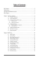
Table of Contents Box Contents....................................................................................................................6 Optional Items..................................................................................................................6 GA-P55A-UD3 Motherboard Layout.................................................................................7 Block Diagram............................................................................................................
Chapter 3 Drivers Installation.........................................................................................61 3-1 3-2 3-3 3-4 3-5 3-6 3-7 Installing Chipset Drivers................................................................................ 61 Application Software....................................................................................... 62 Technical Manuals........................................................................................... 62 Contact.....................
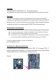
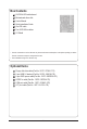
Box Contents GA-P55A-UD3 motherboard Motherboard driver disk User's Manual Quick Installation Guide One IDE cable Two SATA 3Gb/s cables I/O Shield • The box contents above are for reference only and the actual items shall depend on the product package you obtain. The box contents are subject to change without notice. • The motherboard image is for reference only. Optional Items Floppy disk drive cable (Part No. 12CF1-1FD001-7*R) 2-port USB 2.0 bracket (Part No.
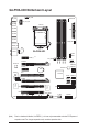
GA-P55A-UD3 Motherboard Layout CPU_FAN KB_USB PHASE LED ATX_12V_2X4 R_SPDIF LGA1156 R_USB3 ATX R_USB2 R_USB1 PWR_FAN USB30_LAN NEC GA-P55A-UD3 M_BIOS B_BIOS PCIEX1_1 (Note) RTL8111D PCIEX1_2 Marvell 9128 SPDIF_I PCI1 GSATA3_6 GSATA3_7 SATA2_3 SATA2_0 PCIEX4 SATA2_4 SATA2_1 SATA2_5 SATA2_2 PCI2 PCI3 LPT FDD IDE CLR_CMOS F_USB1 F_USB2 COMA (Note ) SYS_FAN2 Intel® P55 IT8213 CD_IN IT8720 SPDIF_O BAT CODEC DDR3_3 DDR3_2 SYS_FAN1 PCIEX16 DDR3_4 F_AUDIO DDR3_1 AUDIO F_P
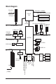
Block Diagram PCIe CLK (100 MHz) CPU CLK+/- (133 MHz) DDR3 2200/1333/1066/800 MHz LGA1156 CPU 1 PCI Express x16 PCI Express x1 DMI Interface x16 Dual Channel Memory 1 PCI Express x4 (PCIEX1_2) PCI Express x1 (PCIEX1_1) PCI Express Bus 2 USB 3.0/2.0 LAN PCIe CLK (100 MHz) NEC 2 SATA 6Gb/s Switch x4 RTL8111D x1 PCI Express Bus x1 RJ45 x1 PCI Express Bus Intel P55 ® Dual BIOS x1 6 SATA 3Gb/s Marvell 9128 12 USB 2.0/1.
Chapter 1 1-1 Hardware Installation Installation Precautions The motherboard contains numerous delicate electronic circuits and components which can become damaged as a result of electrostatic discharge (ESD). Prior to installation, carefully read the user's manual and follow these procedures: • Prior to installation, do not remove or break motherboard S/N (Serial Number) sticker or warranty sticker provided by your dealer. These stickers are required for warranty validation.
1-2 Product Specifications CPU Support for an Intel® Core™ i7 series processor/Intel® Core™ i5 series processor in the LGA1156 package (Go to GIGABYTE's website for the latest CPU support list.) L3 cache varies with CPU Chipset Intel® P55 Express Chipset Memory Audio 4 x 1.
USB Chipset: - Up to 12 USB 2.0/1.1 ports (8 on the back panel, 4 via the USB brackets connected to the internal USB headers) NEC chip: - Up to 2 USB 3.0/2.
BIOS Unique Features w w w w w w w w w w w w w w w w 2 x 16 Mbit flash Use of licensed AWARD BIOS Support for DualBIOS™ PnP 1.0a, DMI 2.0, SM BIOS 2.4, ACPI 1.
1-3 Installing the CPU and CPU Cooler Read the following guidelines before you begin to install the CPU: • Make sure that the motherboard supports the CPU. (Go to GIGABYTE's website for the latest CPU support list.) • Always turn off the computer and unplug the power cord from the power outlet before installing the CPU to prevent hardware damage. • Locate the pin one of the CPU. The CPU cannot be inserted if oriented incorrectly.
B. Follow the steps below to correctly install the CPU into the motherboard CPU socket. Before installing the CPU, make sure to turn off the computer and unplug the power cord from the power outlet to prevent damage to the CPU. Step 1: Gently press the CPU socket lever handle down and away from the socket with your finger. Then completely lift the CPU socket lever and the metal load plate will be lifted as well.
1-3-2 Installing the CPU Cooler Follow the steps below to correctly install the CPU cooler on the motherboard. (The following procedure uses Intel® boxed cooler as the example cooler.) Direction of the Arrow Sign on the Male Push Pin Male Push Pin The Top of Female Push Pin Female Push Pin Step 1: Apply an even and thin layer of thermal grease on the surface of the installed CPU. Step 2: Before installing the cooler, note the direction of the arrow sign on the male push pin.
1-4 Installing the Memory Read the following guidelines before you begin to install the memory: • Make sure that the motherboard supports the memory. It is recommended that memory of the same capacity, brand, speed, and chips be used. (Go to GIGABYTE's website for the latest memory support list.) • Always turn off the computer and unplug the power cord from the power outlet before installing the memory to prevent hardware damage. • Memory modules have a foolproof design.
1-4-2 Installing a Memory Before installing a memory module, make sure to turn off the computer and unplug the power cord from the power outlet to prevent damage to the memory module. DDR3 and DDR2 DIMMs are not compatible to each other or DDR DIMMs. Be sure to install DDR3 DIMMs on this motherboard. Notch DDR3 DIMM A DDR3 memory module has a notch, so it can only fit in one direction. Follow the steps below to correctly install your memory modules in the memory sockets.
1-5 Installing an Expansion Card Read the following guidelines before you begin to install an expansion card: • Make sure the motherboard supports the expansion card. Carefully read the manual that came with your expansion card. • Always turn off the computer and unplug the power cord from the power outlet before installing an expansion card to prevent hardware damage. PCI Express x1 Slot PCI Express x16 Slot PCI Slot Follow the steps below to correctly install your expansion card in the expansion slot.
1-6 Back Panel Connectors USB Port The USB port supports the USB 2.0/1.1 specification. Use this port for USB devices such as a USB keyboard/mouse, USB printer, USB flash drive and etc. PS/2 Keyboard/Mouse Port Use this port to connect a PS/2 keyboard or mouse. Optical S/PDIF Out Connector This connector provides digital audio out to an external audio system that supports digital optical audio. Before using this feature, ensure that your audio system provides an optical digital audio in connector.
Center/Subwoofer Speaker Out Jack (Orange) Use this audio jack to connect center/subwoofer speakers in a 5.1/7.1-channel audio configuration. Rear Speaker Out Jack (Black) Use this audio jack to connect rear speakers in a 4/5.1/7.1-channel audio configuration. Side Speaker Out Jack (Gray) Use this audio jack to connect side speakers in a 7.1-channel audio configuration. Line In Jack (Blue) The default line in jack. Use this audio jack for line in devices such as an optical drive, walkman, etc.
1-7 Internal Connectors 1 3 20 2 5 12 4 10 9 8 13 14 7 15 11 18 1) 2) 3) 4) 5) 6) 7) 8) 9) 10) ATX_12V_2X4 ATX CPU_FAN SYS_FAN1/2 PWR_FAN FDD IDE SATA2_0/1/2/3/4/5 GSATA3_6/7 BAT 17 6 19 11) 12) 13) 14) 15) 16) 17) 18) 19) 20) 16 F_PANEL F_AUDIO CD_IN SPDIF_I SPDIF_O F_USB1/F_USB2 LPT COMA CLR_CMOS PHASE LED Read the following guidelines before connecting external devices: • First make sure your devices are compliant with the connectors you wish to connect.
1/2) ATX_12V_2X4/ATX (2x4 12V Power Connector and 2x12 Main Power Connector) With the use of the power connector, the power supply can supply enough stable power to all the components on the motherboard. Before connecting the power connector, first make sure the power supply is turned off and all devices are properly installed. The power connector possesses a foolproof design. Connect the power supply cable to the power connector in the correct orientation.
3/4/5) CPU_FAN/SYS_FAN1/SYS_FAN2/PWR_FAN (Fan Headers) The motherboard has a 4-pin CPU fan header (CPU_FAN), a 4-pin (SYS_FAN2) and two 3-pin (SYS_ FAN1) system fan headers, and a 3-pin power fan header (PWR_FAN). Most fan headers possess a foolproof insertion design. When connecting a fan cable, be sure to connect it in the correct orientation (the black connector wire is the ground wire). The motherboard supports CPU fan speed control, which requires the use of a CPU fan with fan speed control design.
7) IDE (IDE Connector) The IDE connector supports up to two IDE devices such as hard drives and optical drives. Before attaching the IDE cable, locate the foolproof groove on the connector. If you wish to connect two IDE devices, remember to set the jumpers and the cabling according to the role of the IDE devices (for example, master or slave). (For information about configuring master/slave settings for the IDE devices, read the instructions from the device manufacturers.
9) GSATA3_6/7 (SATA 6Gb/s Connectors, Controlled by Marvell 9128) The SATA connectors conform to SATA 6Gb/s standard and are compatible with SATA 3Gb/s and SATA 1.5Gb/s standards. Each SATA connector supports a single SATA device. G.QBOFM GSATA3_6 1 7 1 7 GSATA3_7 Pin No. 1 2 3 4 5 6 7 Definition GND TXP TXN GND RXN RXP GND Please connect the L-shaped end of the SATA 3Gb/s cable to your SATA hard drive.
11) F_PANEL (Front Panel Header) Connect the power switch, reset switch, speaker, chassis intrusion switch/sensor and system status indicator on the chassis to this header according to the pin assignments below. Note the positive and negative pins before connecting the cables.
12) F_AUDIO (Front Panel Audio Header) The front panel audio header supports Intel High Definition audio (HD) and AC'97 audio. You may connect your chassis front panel audio module to this header. Make sure the wire assignments of the module connector match the pin assignments of the motherboard header. Incorrect connection between the module connector and the motherboard header will make the device unable to work or even damage it. 1 2 9 10 For HD Front Panel Audio: Pin No.
14) SPDIF_I (S/PDIF In Header) This header supports digital S/PDIF In and can connect to an audio device that supports digital audio out via an optional S/PDIF In cable. For purchasing the optional S/PDIF In cable, please contact the local dealer. 1 Pin No.
16) F_USB1/F_USB2 (USB Headers) The headers conform to USB 2.0/1.1 specification. Each USB header can provide two USB ports via an optional USB bracket. For purchasing the optional USB bracket, please contact the local dealer. 9 10 1 2 Pin No. 1 2 3 4 5 6 7 8 9 10 Definition Power (5V) Power (5V) USB DXUSB DYUSB DX+ USB DY+ GND GND No Pin NC • Do not plug the IEEE 1394 bracket (2x5-pin) cable into the USB header.
18) COMA (Serial Port Header) The COMA header can provide one serial port via an optional COM port cable. For purchasing the optional COM port cable, please contact the local dealer. 9 10 1 2 Pin No. 1 2 3 4 5 6 7 8 9 10 Definition NDCDNSIN NSOUT NDTRGND NDSRNRTSNCTSNRINo Pin 19) CLR_CMOS (Clearing CMOS Jumper) Use this jumper to clear the CMOS values (e.g. date information and BIOS configurations) and reset the CMOS values to factory defaults.
20) PHASE LED The number of lighted LEDs indicates the CPU loading. The higher the CPU loading, the more the number of lighted LEDs. To enable the Phase LED display function, please first enable Dynamic Energy Saver™ 2. Refer to Chapter 4, "Dynamic Energy Saver™ 2," for more details.
Hardware Installation - 32 -
Chapter 2 BIOS Setup BIOS (Basic Input and Output System) records hardware parameters of the system in the CMOS on the motherboard. Its major functions include conducting the Power-On Self-Test (POST) during system startup, saving system parameters and loading operating system, etc. BIOS includes a BIOS Setup program that allows the user to modify basic system configuration settings or to activate certain system features.
2-1 Startup Screen The following screens may appear when the computer boots. A. The LOGO Screen (Default) Function Keys B. The POST Screen Award Modular BIOS v6.00PG, An Energy Star Ally Copyright (C) 1984-2009, Award Software, Inc. Motherboard Model BIOS Version P55A-UD3 D4c . . . . : BIOS Setup : XpressRecovery2 : Boot Menu : Qflash 10/08/2009-P55-7A89TG04C-00 Function Keys Function Keys: : POST SCREEN Press the key to show the BIOS POST screen.
2-2 The Main Menu Once you enter the BIOS Setup program, the Main Menu (as shown below) appears on the screen. Use arrow keys to move among the items and press to accept or enter a sub-menu. (Sample BIOS Version: D4c) CMOS Setup Utility-Copyright (C) 1984-2009 Award Software MB Intelligent Tweaker(M.I.T.
The Functions of the and keys (For the Main Menu Only) F11: Save CMOS to BIOS This function allows you to save the current BIOS settings to a profile. You can create up to 8 profiles (Profile 1-8) and name each profile. First enter the profile name (to erase the default profile name, use the SPACE key) and then press to complete.
2-3 MB Intelligent Tweaker(M.I.T.) CMOS Setup Utility-Copyright (C) 1984-2009 Award Software MB Intelligent Tweaker(M.I.T.) M.I.T Current Status Advanced Frequency Settings Advanced Memory Settings Advanced Voltage Settings Miscellaneous Settings } } } } } BIOS Version BCLK CPU Frequency Memory Frequency Total Memory Size D4c 136.73 MHz 2871.48 MHz 1367.34 MHz 2048 MB CPU Temperature PCH Temperature 39.3oC 39.0oC Vcore DRAM Voltage 1.200V 1.
CPU Clock Ratio Allows you to alter the clock ratio for the installed CPU. The adjustable range is dependent on the CPU being installed. CPU Frequency Displays the current operating CPU frequency. Advanced CPU Core Features CMOS Setup Utility-Copyright (C) 1984-2009 Award Software Advanced CPU Core Features Intel(R) Turbo Boost Tech.
C3/C6/C7 State Support (Note) Allows you to determine whether to let the CPU enter C3/C6/C7 mode in system halt state. When enabled, the CPU core frequency and voltage will be reduced during system halt state to decrease power consumption. The C3/C6/C7 state is a more enhanced power-saving state than C1. Auto lets the BIOS automatically configure this setting. (Default: Auto) CPU Thermal Monitor (Note) Enables or disables Intel CPU Thermal Monitor function, a CPU overheating protection function.
BCLK Frequency(Mhz) Allows you to manually set the CPU base clock. The adjustable range is from 100 MHz to 1200 MHz. This item is configurable only if the Base Clock(BCLK) Control option is enabled. Important: It is highly recommended that the CPU frequency be set in accordance with the CPU specifications. Extreme Memory Profile (X.M.P.) (Note) Allows the BIOS when enabled.
CPU Clock Skew Allows you to set the CPU clock prior to the Chipset clock. Options are: 0ps~750ps. (Default: 0ps) Advanced Memory Settings CMOS Setup Utility-Copyright (C) 1984-2009 Award Software Advanced Memory Settings Extreme Memory Profile (X.M.P.
Profile DDR Voltage When using a non-XMP memory module or Extreme Memory Profile (X.M.P.) is set to Disabled, this item will display as 1.5V. When Extreme Memory Profile (X.M.P.) is set to Profile1 or Profile2, this item will display the value based on the SPD data on the XMP memory. Profile QPI Voltage The value displayed here is dependent on the CPU being used. Channel Interleaving Options are: Auto (default), 1~6. Rank Interleaving Options are: Auto (default), 1~4.
tWTR Options are: Auto (default), 1~31. tWR Options are: Auto (default), 1~15. tWTP Options are: Auto (default), 1~31. tWL Options are: Auto (default), 1~10 tRFC Options are: Auto (default), 1~255. tRTP Options are: Auto (default), 1~15. tFAW Options are: Auto (default), 1~63. Command Rate(CMD) Options are: Auto (default), 1~3. >>>>> Channel A/B Misc Timing Control B2B CAS Delay Options are: Auto (default), 1~31. Round Trip Latency Options are: Auto (default), 1~255.
>>> CPU Load-Line Calibration Enables or disables Load-Line Calibration. Enabling this feature adjusts Vdroop, keeping the CPU voltage more constant under light and heavy CPU load. Disabled sets the CPU voltage following Intel specifications. (Default: Disabled) Note: Enabling Load-Line Calibration may result in damage to your CPU or reduce the useful life of the CPU. CPU Vcore The default is Auto. Dynamic Vcore(DVID) The default is Auto. QPI/Vtt Voltage The default is Auto.
Miscellaneous Settings CMOS Setup Utility-Copyright (C) 1984-2009 Award Software Miscellaneous Settings Isochronous Support Virtualization Technology (Note) Enter: Select : Move F5: Previous Values Item Help Menu Level [Enabled] [Enabled] +/-/PU/PD: Value F10: Save F6: Fail-Safe Defaults ESC: Exit F1: General Help F7: Optimized Defaults Isochronous Support Determines whether to enable specific streams within the CPU and Chipset.
2-4 Standard CMOS Features CMOS Setup Utility-Copyright (C) 1984-2009 Award Software Standard CMOS Features } } } } } } } } } } } Date (mm:dd:yy) Time (hh:mm:ss) Thu, Oct 8 2009 22:31:24 IDE Channel 0 Master IDE Channel 0 Slave IDE Channel 1 Master IDE Channel 1 Slave IDE Channel 2 Master IDE Channel 3 Master IDE Channel 4 Master IDE Channel 4 Slave IDE Channel 6 Master IDE Channel 6 Slave IDE Channel 7 Master [None] [None] [None] [None] [None] [None] [None] [N
• None • Auto • Manual Access Mode If no IDE/SATA devices are used, set this item to None so the system will skip the detection of the device during the POST for faster system startup. Lets the BIOS automatically detect IDE/SATA devices during the POST. (Default) Allows you to manually enter the specifications of the hard drive when the hard drive access mode is set to CHS. Sets the hard drive access mode. Options are: Auto (default), CHS, LBA, Large.
2-5 Advanced BIOS Features CMOS Setup Utility-Copyright (C) 1984-2009 Award Software Advanced BIOS Features } Hard Disk Boot Priority Quick Boot First Boot Device Second Boot Device Third Boot Device Password Check HDD S.M.A.R.T. Capability Limit CPUID Max.
Limit CPUID Max. to 3 (Note) Allows you to determine whether to limit CPUID maximum value. Set this item to Disabled for Windows XP operating system; set this item to Enabled for legacy operating system such as Windows NT4.0. (Default: Disabled) No-Execute Memory Protect (Note) Enables or disables Intel Execute Disable Bit function. This function may enhance protection for the computer, reducing exposure to viruses and malicious buffer overflow attacks when working with its supporting software and system.
2-6 Integrated Peripherals CMOS Setup Utility-Copyright (C) 1984-2009 Award Software Integrated Peripherals eXtreme Hard Drive (XHD) PCH SATA Control Mode SATA Port0-3 Native Mode USB Controllers USB Legacy Function USB Storage Function Turbo SATA3/USB 3.0 Azalia Codec Onboard H/W LAN Green LAN } SMART LAN Onboard LAN Boot ROM Onboard USB 3.
USB Legacy Function Allows USB keyboard to be used in MS-DOS. (Default: Enabled) USB Storage Function Determines whether to detect USB storage devices, including USB flash drives and USB hard drives during the POST. (Default: Enabled) Turbo SATA3 / USB3.0 (Marvell 9128 /NEC USB 3.0 Controller) Determines whether to set the PCIe speed of the Marvell 9128 or NEC USB 3.0 controller to PCIe Gen 2.
SMART LAN CMOS Setup Utility-Copyright (C) 1984-2009 Award Software SMART LAN Start detecting at Port.....
Onboard LAN Boot ROM Allows you to decide whether to activate the boot ROM integrated with the onboard LAN chip. (Default: Disabled) Onboard USB 3.0 Controller (NEC Chip) Enables or disables the integrated USB 3.0 controller. (Default: Enabled) Onboard IDE Controller (IT8213 Chip) Enables or disables the IDE controller integrated in the IT8213 chip.
2-7 Power Management Setup CMOS Setup Utility-Copyright (C) 1984-2009 Award Software Power Management Setup ACPI Suspend Type Soft-Off by PWR-BTTN PME Event Wake Up Power On by Ring Resume by Alarm x Date (of Month) Alarm x Time (hh:mm:ss) Alarm HPET Support (Note) HPET Mode (Note) Power On By Mouse Power On By Keyboard x KB Power ON Password AC Back Function EuP Support Enter: Select : Move F5: Previous Values [S3(STR)] [Instant-Off] [Enabled] [Enabled] [Disa
Resume by Alarm Determines whether to power on the system at a desired time. (Default: Disabled) If enabled, set the date and time as following: Date (of Month) Alarm: Turn on the system at a specific time on each day or on a specific day in a month. Time (hh: mm: ss) Alarm: Set the time at which the system will be powered on automatically. Note: When using this function, avoid inadequate shutdown from the operating system or removal of the AC power, or the settings may not be effective.
2-8 PC Health Status CMOS Setup Utility-Copyright (C) 1984-2009 Award Software PC Health Status Reset Case Open Status Case Opened Vcore DDR15V +5V +12V Current System Temperature Current CPU Temperature Current CPU FAN Speed Current SYSTEM FAN2 Speed Current POWER FAN Speed Current SYSTEM FAN1 Speed CPU Warning Temperature CPU FAN Fail Warning SYSTEM FAN2 Fail Warning POWER FAN Fail Warning SYSTEM FAN1 Fail Warning CPU Smart FAN Control CPU Smart FAN M
CPU Smart FAN Control Specifies how to control CPU fan speed. This item is configurable only if CPU Smart FAN Control is set to Enabled. Auto Lets the BIOS automatically detect the type of CPU fan installed and sets the optimal CPU fan control mode. (Default) Voltage Sets Voltage mode for a 3-pin CPU fan. PWM Sets PWM mode for a 4-pin CPU fan. Note: The Voltage mode can be set for a 3-pin CPU fan or a 4-pin CPU fan.
2-9 Load Fail-Safe Defaults CMOS Setup Utility-Copyright (C) 1984-2009 Award Software MB Intelligent Tweaker(M.I.T.
2-11 Set Supervisor/User Password CMOS Setup Utility-Copyright (C) 1984-2009 Award Software MB Intelligent Tweaker(M.I.T.
2-12 Save & Exit Setup CMOS Setup Utility-Copyright (C) 1984-2009 Award Software MB Intelligent Tweaker(M.I.T.
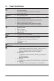
Chapter 3 Drivers Installation • Before installing the drivers, first install the operating system. • After installing the operating system, insert the motherboard driver disk into your optical drive. The driver Autorun screen is automatically displayed which looks like that shown in the screen shot below. (If the driver Autorun screen does not appear automatically, go to My Computer, double-click the optical drive and execute the Run.exe program.
3-2 Application Software This page displays all the utilities and applications that GIGABYTE develops and some free software. You can click the Install button on the right of an item to install it. 3-3 Technical Manuals This page provides GIGABYTE's application guides, content descriptions for this driver disk, and the motherboard manuals.
3-4 Contact For the detailed contact information of the GIGABYTE Taiwan headquarter or worldwide branch offices, click the URL on this page to link to the GIGABYTE website. 3-5 System This page provides the basic system information.
3-6 Download Center To update the BIOS, drivers, or applications, click the Download Center button to link to the GIGABYTE website. The latest version of the BIOS, drivers, or applications will be displayed. 3-7 New Utilities This page provides a quick link to GIGABYTE's lately developed utilities for users to install. You can click the Install button on the right of an item to install it.
Chapter 4 4-1 Unique Features Xpress Recovery2 Xpress Recovery2 is a utility that allows you to quickly compress and back up your system data and perform restoration of it. Supporting NTFS, FAT32, and FAT16 file systems, Xpress Recovery2 can back up data on PATA and SATA hard drives and restore it. Before You Begin: • Xpress Recovery2 will check the first physical hard drive(Note) for the operating system.
Step 3: When partitioning your hard drive, make sure to leave unallocated space (10 GB or more is recommended; actual size requirements vary, depending on the amount of data) and begin the installation of the operating system. Step 4: After the operating system is installed, right-click the Computer icon on your desktop and select Manage. Go to Disk Management to check disk allocation. Step 5: Xpress Recovery2 will save the backup file to the unallocated space (black stripe along the top).
D. Using the Restore Function in Xpress Recovery2 Select RESTORE to restore the backup to your hard drive in case the system breaks down. The RESTORE option will not be present if no backup is created before. E. Removing the Backup Step 1: If you wish to remove the backup file, select REMOVE. Step 2: After the backup file is removed, no backup image file will be present in Disk Management and hard drive space will be freed up. F. Exiting Xpress Recovery2 Select REBOOT to exit Xpress Recovery2.
4-2 BIOS Update Utilities GIGABYTE motherboards provide two unique BIOS update tools, Q-Flash™ and @BIOS™. GIGABYTE Q-Flash and @BIOS are easy-to-use and allow you to update the BIOS without the need to enter MS-DOS mode. Additionally, this motherboard features the DualBIOS™ design, which enhances protection for the safety and stability of your computer by adding one more physical BIOS chip. What is DualBIOS™? Motherboards that support DualBIOS have two BIOS onboard, a main BIOS and a backup BIOS.
B. Updating the BIOS When updating the BIOS, choose the location where the BIOS file is saved. The following procedure assumes that you save the BIOS file to a floppy disk. Step 1: 1. Insert the floppy disk containing the BIOS file into the floppy disk drive. In the main menu of Q-Flash, use the up or down arrow key to select Update BIOS from Drive and press . • The Save Main BIOS to Drive option allows you to save the current BIOS file.
Step 4: Press and then to exit Q-Flash and reboot the system. As the system boots, you should see the new BIOS version is present on the POST screen. Step 5: During the POST, press to enter BIOS Setup. Select Load Optimized Defaults and press to load BIOS defaults. System will re-detect all peripheral devices after a BIOS update, so we recommend that you reload BIOS defaults. CMOS Setup Utility-Copyright (C) 1984-2009 Award Software MB Intelligent Tweaker(M.I.T.
4-2-2 Updating the BIOS with the @BIOS Utility A. Before You Begin 1. 2. 3. 4. In Windows, close all applications and TSR (Terminate and Stay Resident) programs. This helps prevent unexpected failures when performing a BIOS update. During the BIOS update process, ensure the Internet connection is stable and do NOT interrupt the Internet connection (for example, avoid a power loss or switching off the Internet). Failure to do so may result in a corrupted BIOS or a system that is unable to start.
4-3 EasyTune 6 GIGABYTE's EasyTune 6 is a simple and easy-to-use interface that allows users to fine-tune their system settings or do overclock/overvoltage in Windows environment. The user-friendly EasyTune 6 interface also includes tabbed pages for CPU and memory information, letting users read their system-related information without the need to install additional software.
4-4 Dynamic Energy Saver™ 2 GIGABYTE Dynamic Energy Saver™ 2 (Note 1) is a revolutionary technology that delivers unparalleled power savings with a click of the button. Featuring an advanced proprietary hardware and software design, GIGABYTE Dynamic Energy Saver™ 2 is able to provide exceptional power savings and enhanced power efficiency without sacrificing computing performance. The Dynamic Energy Saver™ 2 Interface A.
B. Total Mode In Total Mode, users are able to see how much total power savings they have accumulated in a set period of time since activating Dynamic Energy Saver™ 2 for the first time (Note 3).
4-5 Q-Share Q-Share is an easy and convenient data sharing tool. After configuring your LAN connection settings and Q-Share, you are able to share your data with computers on the same network, making full use of Internet resources. Directions for using Q-Share After installing Q-Share from the motherboard driver disk, go to Start>All Programs>GIGABYTE>Q-Share. exe to launch the Q-Share tool.
4-6 Smart 6™ GIGABYTE Smart 6™ (Note 1) is designed with user-friendliness in mind, and offers a combination of 6 innovative software utilities that provide easier and smarter PC system management. Smart 6™ allows you to speed up system performance, reduce boot-up time, manage a secure platform and recover specified files easily with a click of the mouse button.
SMART Recovery With SMART Recovery, users can quickly create backups of changed data files (Note 2) or copy files from a specific backup on PATA and SATA hard drives (partitioned on NTFS file system) in Windows Vista. Instructions: In the main menu, click the Config button to open the Smart Recovery Preference dialog box.
SMART Recorder SMART Recorder monitors and records the activities in a system such as the time when the computer was turned on/off or even when large data files were moved within the hard drive or copied to an external storage device (Note 5). Instructions: Select the Enable check box at the bottom of the ON/OFF Recorder or File Monitor tab to enable the recording of system on/off time or files copying. Entering the Smart 6™ password is required before you make any changes to the previous settings.
4-7 Auto Green Auto Green is an easy-to-use tool that provides users with simple options to enable system power savings via a Bluetooth cell phone. When the phone is out of the range of the computer's Bluetooth receiver, the system will enter the specified power saving mode. The Configuration dialog box: First, you have to set your Bluetooth cell phone as a portable key. On the Auto Green main menu, click Configure and then click Configure BT devices.
4-8 eXtreme Hard Drive (X.H.D) With GIGABYTE eXtreme Hard Drive (X.H.D)(Note 1), users can quickly configure a RAIDready system for RAID 0 when a new SATA drive is added. For a RAID 0 array that already exists, users also can use X.H.D to easily add a hard drive into the array to expand its capacity. All with a simple click of a button, X.H.D helps to enhance your hard drive read/write performance without the need for complex and time-consuming configurations.
Chapter 5 5-1 Appendix Configuring SATA Hard Drive(s) To configure SATA hard drive(s), follow the steps below: A. B. C. D. E. Install SATA hard drive(s) in your computer. Configure SATA controller mode in BIOS Setup. Configure a RAID array in RAID BIOS. (Note 1) Make a floppy disk containing the SATA RAID/AHCI driver for Windows XP. (Note 2) Install the SATA RAID/AHCI driver and operating system.
B. Configuring SATA controller mode in BIOS Setup Make sure to configure the SATA controller mode correctly in system BIOS Setup. Step 1: Turn on your computer and press to enter BIOS Setup during the POST (Power-On Self-Test). To create RAID, set PCH SATA Control Mode under the Integrated Peripherals menu to RAID(XHD) (Figure 1) (Disabled by default). If you do not want to create RAID, set this item to Disabled or AHCI.
C. Configuring a RAID array in RAID BIOS Enter the RAID BIOS setup utility to configure a RAID array. Skip this step and proceed with the installation of Windows operating system for a non-RAID configuration. Step 1: After the POST memory test begins and before the operating system boot begins, look for a message which says "Press to enter Configuration Utility" (Figure 2). Press + to enter the P55 RAID Configuration Utility. Intel(R) Matrix Storage Manager option ROM v8.9.0.
Step 3: After entering the CREATE VOLUME MENU screen, enter a volume name with 1~16 letters (letters cannot be special characters) under the Name item and press . Then, select a RAID level (Figure 4). RAID levels supported include RAID 0, RAID 1, Recovery, RAID 10, and RAID 5 (the selections available depend on the number of the hard drives being installed). Press to proceed. Intel(R) Matrix Storage Manager option ROM v8.9.0.1023 PCH-D wRAID5 Copyright(C) 2003-09 Intel Corporation.
Step 5: Enter the array capacity and press . Finally press on the Create Volume item to begin creating the RAID array. When prompted to confirm whether to create this volume, press to confirm or to cancel (Figure 6). Intel(R) Matrix Storage Manager option ROM v8.9.0.1023 PCH-D wRAID5 Copyright(C) 2003-09 Intel Corporation. All Rights Reserved. [ CREATE VOLUME MENU ] Name : Volume0 RAID Level : RAID0(Stripe) Disks : Select Disks Strip Size : 128 MB Capacity : 111.
Recovery Volume Options Intel Rapid Recover Technology provides data protection by allowing users to easily restore data and system operation using a designated recovery drive. With the Rapid Recovery Technology, which employs RAID 1 functionality, users can copy the data from the master drive to the recovery drive; if needed, the data on the recovery drive can be restored back to the master drive. Before you begin: • The recovery drive must have equal or greater capacity than the master drive.
Step 3: Press under the Select Disks item. In the SELECT DISKS box, press on the hard drive you want to use for the master drive and press on the hard drive you want to use for the recovery drive. (Make sure the recovery drive has equal or larger capacity than the master drive.) Then press to confirm. (Figure 10) Intel(R) Matrix Storage Manager option ROM v8.9.0.1023 PCH-D wRAID5 Copyright(C) 2003-09 Intel Corporation. All Rights Reserved.
Delete RAID Volume To delete a RAID array, select Delete RAID Volume in MAIN MENU and press . In the DELETE VOLUME MENU section, use the up or down arrow key to select the array to be deleted and press . When prompted to confirm your selection (Figure 12), press to confirm or to abort. Intel(R) Matrix Storage Manager option ROM v8.9.0.1023 PCH-D wRAID5 Copyright(C) 2003-09 Intel Corporation. All Rights Reserved.
5-1-2 Making a SATA RAID/AHCI Driver Diskette (Required for AHCI and RAID Mode) To successfully install operating system onto SATA hard drive(s) that is/are configured to RAID/AHCI mode, you need to install the SATA controller driver during the OS installation. Without the driver, the hard drive may not be recognized during the Windows setup process. First of all, copy the driver for the SATA controller from the motherboard driver disk to a floppy disk.
5-1-4 Installing the SATA RAID/AHCI Driver and Operating System With the SATA RAID/AHCI driver diskette and correct BIOS settings, you are ready to install Windows Vista/ XP onto your hard drive(s). The followings are examples of Windows XP and Vista installation. A. Installing Windows XP Step 1: Restart your system to boot from the Windows XP setup disk and press as soon as you see the message "Press F6 if you need to install a 3rd party SCSI or RAID driver" (Figure 1).
B. Installing Windows Vista (The procedure below assumes that only one RAID array exists in your system.) For the Intel P55: Step 1: Restart your system to boot from the Windows Vista setup disk and perform standard OS installation steps. When a screen similar to that below appears, select Load Driver (Figure 4). Figure 4 Step 2: Insert the motherboard driver disk (Method A) or the floppy disk/USB flash drive that contains the driver (Method B), then specify the location of the driver (Figure 5).
Step 3: When a screen as shown in Figure 6 appears, select Intel(R) ICH8R/ICH9R/ICH10R/DO/PCH SATA RAID Controller and click Next. Figure 6 Step 4: After the driver is loaded, select the RAID/AHCI drive(s) where you want to install the operating system and then click Next to continue the OS installation (Figure 7).
C. Rebuilding an Array Rebuilding is the process of restoring data to a hard drive from other drives in the array. Rebuilding applies only to fault-tolerant arrays such as RAID 1, RAID 5 or RAID 10 arrays. The procedures below assume a new drive is added to replace a failed drive to rebuild a RAID 1 array. (Note: The new drive must have equal or greater capacity than the old one.) For the Intel P55: Turn off your computer and replace the failed hard drive with a new one. Restart your computer.
• Performing the Rebuild in the Operating System While in the operating system, make sure the chipset driver has been installed from the motherboard driver disk. Then launch the Intel Matrix Storage Console from All Programs in the Start menu. Step 1: On the View menu of the Intel Matrix Storage Console, select Advanced Mode for a more detailed view of the storage device information. Step 2: The new hard drive appears under Non-RAID Hard Drive.
• Restoring the Master Drive to a Previous State (for Recovery Volume only) When two hard drives are set to Recovery Volume in Update on Request mode, you can restore the master drive data to the last backup state when needed. For example, in case the master drive detects a virus, you can restore the recovery drive data to the master drive. Step 1: Select 4. Recovery Volume Options in the MAIN MENU of the P55 RAID Configuration Utility.
5-2 Configuring Audio Input and Output 5-2-1 Configuring 2/4/5.1/7.1-Channel Audio The motherboard provides six audio jacks on the back panel which support 2/4/5.1/7.1-channel (Note) audio. The picture to the right shows the default audio Center/Subwoofer Line In Speaker Out jack assignments.
Step 2: Connect an audio device to an audio jack. The The current connected device is dialog box appears. Select the device according to the type of device you connect. Then click OK. Step 3: On the Speakers screen, click the Speaker Configuration tab. In the Speaker Configuration list, select Stereo, Quadraphonic, 5.1 Speaker, or 7.1 Speaker according to the type of speaker configuration you wish to set up. Then the speaker setup is completed. B.
5-2-2 Configuring S/PDIF In/Out A. S/PDIF In The S/PDIF In cable (optional) allows you to input digital audio signals to the computer for audio processing. S/PDIF In Cable Optical S/PDIF In Coaxial S/PDIF In 1. Installing the S/PDIF In Cable: Step 1: First, attach the connector at the end of the cable to the SPDIF_I header on your motherboard. Step 2: Secure the metal bracket to the chassis back panel with a screw. 2.
B. S/PDIF Out The S/PDIF Out jacks can transmit audio signals to an external decoder for decoding to get the best audio quality. 1. Connecting a S/PDIF Out Cable: S/PDIF Coaxial Cable S/PDIF Optical Cable Connect a S/PDIF coaxial cable or a S/PDIF optical cable (either one) to an external decoder for transmitting the S/PDIF digital audio signals. 2. Configuring S/PDIF Out: On the Digital Output screen, click the Default Format tab and then select the sample rate and bit depth. Click OK to complete.
5-2-3 Configuring Microphone Recording Step 1: After installing the audio driver, the HD Audio Manager icon will appear in the notification area. Double-click the icon to access the HD Audio Manager. Step 2: Connect your microphone to the Mic in jack (pink) on the back panel or the Mic in jack (pink) on the front panel. Then configure the jack for microphone functionality. Note: The microphone functions on the front panel and back panel cannot be used at the same time. Step 3: Go to the Microphone screen.
Step 4: To raise the recording and playback volume for the microphone, click the Microphone Boost icon on the right of the Recording Volume slider and set the Microphone Boost level. Step 5: After completing the settings above, click Start, point to All Programs, point to Accessories, and then click Sound Recorder to begin the sound recording. * Enabling Stereo Mix If the HD Audio Manager does not display the recording device you wish to use, refer to the steps below.
Step 3: When the Stereo Mix item appears, right-click on this item and select Enable. Then set it as the default device. Step 4: Now you can access the HD Audio Manager to configure Stereo Mix and use Sound Recorder to record the sound. 5-2-4 Using the Sound Recorder A. Recording Sound 1. Make sure you have connected the sound input device (e.g. microphone) to the computer. 2. To record the audio, click the Start Recording button . 3. To stop recording audio, click the Stop Recording button .
5-3 Troubleshooting 5-3-1 Frequently Asked Questions To read more FAQs for your motherboard, please go to the Support&Downloads\Motherboard\FAQ page on GIGABYTE's website. Q: In the BIOS Setup program, why are some BIOS options missing? A: Some advanced options are hidden in the BIOS Setup program. Press to enter BIOS Setup during the POST. In the Main Menu, press + to show the advanced options.
5-3-2 Troubleshooting Procedure If you encounter any troubles during system startup, follow the troubleshooting procedure below to solve the problem. START Turn off the power. Remove all peripherals, connecting cables, and power cord etc. Make sure the motherboard does not short-circuit with the chassis or other metal objects. No Yes The problem is verified and solved. Check if the CPU cooler is attached to the CPU securely.
A When the computer is turned on, is the CPU cooler running? Yes No The power supply, CPU or CPU socket might fail. The problem is verified and solved. Check if there is display on your monitor. Yes No The graphics card, expansion slot, or monitor might fail. The problem is verified and solved. Turn off the computer. Plug in the keyboard and mouse and restart the computer. Check if the keyboard is working properly. Yes No The keyboard or keyboard connector might fail.
5-4 Regulatory Statements Regulatory Notices This document must not be copied without our written permission, and the contents there of must not be imparted to a third party nor be used for any unauthorized purpose. Contravention will be prosecuted. We believe that the information contained herein was accurate in all respects at the time of printing. GIGABYTE cannot, however, assume any responsibility for errors or omissions in this text.
Finally, we suggest that you practice other environmentally friendly actions by understanding and using the energy-saving features of this product (where applicable), recycling the inner and outer packaging (including shipping containers) this product was delivered in, and by disposing of or recycling used batteries properly.
Appendix - 108 -
- 109 - Appendix
Appendix - 110 -
Contact Us • GIGA-BYTE TECHNOLOGY CO., LTD. Address: No.6, Bau Chiang Road, Hsin-Tien, Taipei 231, Taiwan TEL: +886-2-8912-4000 FAX: +886-2-8912-4003 Tech. and Non-Tech. Support (Sales/Marketing) : http://ggts.gigabyte.com.tw WEB address (English): http://www.gigabyte.com.tw WEB address (Chinese): http://www.gigabyte.tw • G.B.T. INC. - U.S.A. TEL: +1-626-854-9338 FAX: +1-626-854-9339 Tech. Support: http://rma.gigabyte.us Web address: http://www.gigabyte.us • G.B.T.
• G.B.T. TECHNOLOGY TRADING GMBH - Germany WEB address : http://www.gigabyte.de • G.B.T. TECH. CO., LTD. - U.K. WEB address : http://www.giga-byte.co.uk • Giga-Byte Technology B.V. - The Netherlands WEB address : http://www.giga-byte.nl • GIGABYTE TECHNOLOGY FRANCE - France WEB address : http://www.gigabyte.fr • Sweden WEB address : http://www.gigabyte.se • Italy WEB address : http://www.giga-byte.it • Spain WEB address : http://www.giga-byte.es • Greece WEB address : http://www.gigabyte.com.