GA-P61-S3 User's Manual Rev.
Motherboard GA-P61-S3 Nov. 30, 2011 Motherboard GA-P61-S3 Nov.
Copyright © 2011 GIGA-BYTE TECHNOLOGY CO., LTD. All rights reserved. The trademarks mentioned in this manual are legally registered to their respective owners. Disclaimer Information in this manual is protected by copyright laws and is the property of GIGABYTE. Changes to the specifications and features in this manual may be made by GIGABYTE without prior notice.
Table of Contents GA-P61-S3 Motherboard Layout.....................................................................................5 GA-P61-S3 Motherboard Block Diagram.........................................................................6 Chapter 1 Hardware Installation......................................................................................7 1-1 1-2 1-3 1-4 1-5 1-6 1-7 Installation Precautions....................................................................................
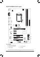
GA-P61-S3 Motherboard Layout KB_MS CPU_FAN ATX_12V COMA LGA1155 R_USB ATX USB_LAN F_AUDIO PWR_FAN Atheros/Realtek GbE LAN CODEC PCIEX16 BAT GA-P61-S3 DDR3_2 SYS_FAN1 DDR3_1 AUDIO PCIEX1_1 Intel® H61 PCIEX1_2 SPDIF_O SATA2 PCI1 3 1 2 0 PCI2 iTE IT8728 M_BIOS PCIe to PCI Bridge PCI3 SYS_FAN2 F_USB2 F_USB1 B_BIOS CLR_CMOS F_PANEL Box Contents 55 GA-P61-S3 motherboard 55 Motherboard driver disk 55 User's Manual 55 Two SATA cables 55 I/O Shield * The box contents above are for re
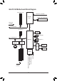
GA-P61-S3 Motherboard Block Diagram 1 PCI Express x16 CPU CLK+/- (100 MHz) LGA1155 CPU DDR3 1333/1066/800 MHz Dual Channel Memory PCIe CLK (100 MHz) DMI 2.0 x16 PCI Express Bus 2 PCI Express x1 Dual BIOS PCI Express Bus x1 x1 Atheros/Realtek GbE LAN RJ45 4 SATA 3Gb/s x1 8 USB 2.0/1.
Chapter 1 1-1 Hardware Installation Installation Precautions The motherboard contains numerous delicate electronic circuits and components which can become damaged as a result of electrostatic discharge (ESD). Prior to installation, carefully read the user's manual and follow these procedures: •• Prior to installation, make sure the chassis is suitable for the motherboard. •• Prior to installation, do not remove or break motherboard S/N (Serial Number) sticker or warranty sticker provided by your dealer.
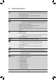
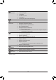
1-2 Product Specifications CPU Support for Intel® Core™ i7 processors/Intel® Core™ i5 processors/ Intel® Core™ i3 processors/Intel® Pentium® processors/Intel® Celeron® processors in the LGA1155 package (Go to GIGABYTE's website for the latest CPU support list.) L3 cache varies with CPU Chipset Intel® H61 Express Chipset Memory 2 x 1.
Back Panel Connectors 1 x PS/2 keyboard port 1 x PS/2 mouse port 1 x serial port 4 x USB 2.0/1.
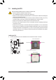
1-3 Installing the CPU Read the following guidelines before you begin to install the CPU: •• Make sure that the motherboard supports the CPU. (Go to GIGABYTE's website for the latest CPU support list.) •• Always turn off the computer and unplug the power cord from the power outlet before installing the CPU to prevent hardware damage. •• Locate the pin one of the CPU. The CPU cannot be inserted if oriented incorrectly.
1-4 Installing the Memory Read the following guidelines before you begin to install the memory: •• Make sure that the motherboard supports the memory. It is recommended that memory of the same capacity, brand, speed, and chips be used. (Go to GIGABYTE's website for the latest supported memory speeds and memory modules.) •• Always turn off the computer and unplug the power cord from the power outlet before installing the memory to prevent hardware damage. •• Memory modules have a foolproof design.
1-6 Back Panel Connectors PS/2 Keyboard and PS/2 Mouse Port Use the upper port (green) to connect a PS/2 mouse and the lower port (purple) to connect a PS/2 keyboard. Serial Port Use the serial port to connect devices such as a mouse, modem or other peripherals. USB 2.0/1.1 Port The USB port supports the USB 2.0/1.1 specification. Use this port for USB devices such as a USB keyboard/mouse, USB printer, USB flash drive and etc.
1-7 Internal Connectors 1 3 2 12 4 5 8 10 6 4 1) 2) 3) 4) 5) 6) ATX_12V ATX CPU_FAN SYS_FAN1/2 PWR_FAN SATA2 0/1/2/3 9 11 7) 8) 9) 10) 11) 12) 7 F_PANEL F_AUDIO F_USB1/2 SPDIF_O CLR_CMOS BAT Read the following guidelines before connecting external devices: •• First make sure your devices are compliant with the connectors you wish to connect. •• Before installing the devices, be sure to turn off the devices and your computer.
1/2) ATX_12V/ATX (2x2 12V Power Connector and 2x12 Main Power Connector) With the use of the power connector, the power supply can supply enough stable power to all the components on the motherboard. Before connecting the power connector, first make sure the power supply is turned off and all devices are properly installed. The power connector possesses a foolproof design. Connect the power supply cable to the power connector in the correct orientation.
3/4/5) CPU_FAN/SYS_FAN1/SYS_FAN2/PWR_FAN (Fan Headers) The motherboard has a 4-pin CPU fan header (CPU_FAN), a 4-pin (SYS_FAN2) and a 3-pin (SYS_FAN1) system fan headers, and a 3-pin power fan header (PWR_FAN). Most fan headers possess a foolproof insertion design. When connecting a fan cable, be sure to connect it in the correct orientation (the black connector wire is the ground wire). The speed control function requires the use of a fan with fan speed control design.
7) F_PANEL (Front Panel Header) Connect the power switch, reset switch, speaker, chassis intrusion switch/sensor and system status indicator on the chassis to this header according to the pin assignments below. Note the positive and negative pins before connecting the cables.
8) F_AUDIO (Front Panel Audio Header) The front panel audio header supports Intel High Definition audio (HD) and AC'97 audio. You may connect your chassis front panel audio module to this header. Make sure the wire assignments of the module connector match the pin assignments of the motherboard header. Incorrect connection between the module connector and the motherboard header will make the device unable to work or even damage it. For HD Front Panel Audio: Pin No.
10) SPDIF_O (S/PDIF Out Header) This header supports digital S/PDIF Out and connects a S/PDIF digital audio cable (provided by expansion cards) for digital audio output from your motherboard to certain expansion cards like graphics cards and sound cards.
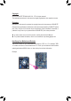
12) BAT (Battery) The battery provides power to keep the values (such as BIOS configurations, date, and time information) in the CMOS when the computer is turned off. Replace the battery when the battery voltage drops to a low level, or the CMOS values may not be accurate or may be lost. You may clear the CMOS values by removing the battery: 1. Turn off your computer and unplug the power cord. 2. Gently remove the battery from the battery holder and wait for one minute.
Chapter 2 BIOS Setup BIOS (Basic Input and Output System) records hardware parameters of the system in the CMOS on the motherboard. Its major functions include conducting the Power-On Self-Test (POST) during system startup, saving system parameters and loading operating system, etc. BIOS includes a BIOS Setup program that allows the user to modify basic system configuration settings or to activate certain system features.
2-2 The Main Menu On the main menu of the BIOS Setup program, press arrow keys to move among the items and press to accept or enter a sub-menu. Or you can use your mouse to select the item you want. (Sample BIOS Version: F1a) Setup Menus Enter Q-Flash Select Default Language Help Function Keys Configuration Items Current Settings BIOS Setup Menus M.I.T. Use this menu to configure the clock, frequency, and voltages of your CPU and memory, etc.
2-3 M.I.T. Whether the system will work stably with the overclock/overvoltage settings you made is dependent on your overall system configurations. Incorrectly doing overclock/overvoltage may result in damage to CPU, chipset, or memory and reduce the useful life of these components. This page is for advanced users only and we recommend you not to alter the default settings to prevent system instability or other unexpected results. (Inadequately altering the settings may result in system's failure to boot.
`` M.I.T. Current Status This screen provides information on CPU/memory frequencies/parameters. `` Advanced Frequency Settings && CPU Clock Ratio Allows you to alter the clock ratio for the installed CPU. The adjustable range is dependent on the CPU being installed. && CPU Frequency Displays the current operating CPU frequency.
&& CPU Clock Ratio, CPU Frequency The settings under the two items above are synchronous to that under the same items on the Advanced Frequency Settings menu. && Internal CPU PLL Overvoltage Enabled allows CPU PLL voltage to operate at a higher value. Disabled allows CPU PLL voltage to operate at default value. Auto lets the BIOS automatically configure this setting.
&& CPU EIST Function (Note) Enables or disables Enhanced Intel SpeedStep Technology (EIST). Depending on CPU loading, Intel EIST technology can dynamically and effectively lower the CPU voltage and core frequency to decrease average power consumption and heat production. Auto lets the BIOS automatically configure this setting. (Default: Auto) && Bi-Directional PROCHOT (Note) Auto Lets BIOS automatically configure this setting.
&& System Memory Multiplier, Memory Frequency(Mhz) The settings under the two items above are synchronous to those under the same items on the Advanced Frequency Settings menu. && Performance Enhance Allows the system to operate at three different performance levels. Normal Lets the system operate at its basic performance level. Turbo Lets the system operate at its good performance level. (Default) Extreme Lets the system operate at its best performance level.
`` Advanced Voltage Settings && CPU Vtt Allows you to set CPU Vtt voltage. The default is Auto. && DRAM Voltage Allows you to set memory voltage. The default is Auto.
&& Reset Case Open Status Disabled Keeps or clears the record of previous chassis intrusion status. (Default) Enabled Clears the record of previous chassis intrusion status and the Case Opened field will show "No" at next boot. && Case Opened Displays the detection status of the chassis intrusion detection device attached to the motherboard CI header. If the system chassis cover is removed, this field will show "Yes", otherwise it will show "No".
&& Slope PWM Allows you to control the CPU fan speed. This item is configurable only when CPU Fan Speed Control is set to Manual. Options are: 0.75 PWM value /oC ~ 2.50 PWM value /oC. && 1st System Fan Speed Control (SYS_FAN1 Connector) Allows you to determine whether to enable the system fan speed control function for the system fan connected to the SYS_FAN1 connector and adjust the fan speed. Normal Allows the system fan to run at different speeds according to the system temperature.
&& Isochronous Support Determines whether to enable specific streams within the CPU and Chipset. This item is present only when you install a CPU that supports this feature. For more information about Intel CPUs' unique features, please visit Intel's website. (Default: Enabled) 2-4 System This section provides information on your motherboard model and BIOS version. You can also select the default language used by the BIOS and manually set the system time.
2-5 BIOS Features && Boot Option Priorities Specifies the overall boot order from the available devices. For example, you can set hard drive as the first priority (Boot Option #1) and DVD ROM drive as the second priority (Boot Option #2). The list only displays the device with the highest priority for a specific type. For example, only hard drive defined as the first priority on the Hard Drive BBS Priorities submenu will be presented here.
&& Execute Disable Bit (Note) Enables or disables Intel Execute Disable Bit function. This function may enhance protection for the computer, reducing exposure to viruses and malicious buffer overflow attacks when working with its supporting software and system. (Default: Enabled) && Intel Virtualization Technology (Note) Enables or disables Intel Virtualization Technology.
&& SATA Controller(s) (Intel H61 Chipset) Enables or disables the integrated SATA controllers. (Default: Enabled) && SATA Mode Selection (Intel H61 Chipset) Allows you to decide whether to configure the SATA controllers integrated in the Intel H61 Chipset to AHCI mode. IDE Configures the SATA controllers to IDE mode. (Default) AHCI Configures the SATA controllers to AHCI mode.
2-7 Power Management && AC BACK Determines the state of the system after the return of power from an AC power loss. Memory The system returns to its last known awake state upon the return of the AC power. Always On The system is turned on upon the return of the AC power. Always Off The system stays off upon the return of the AC power. (Default) && Power On By Keyboard Allows the system to be turned on by a PS/2 keyboard wake-up event.
&& ErP Determines whether to let the system consume less than 1W power in S5 (shutdown) state. (Default: Disabled) Note: When this item is set to Enabled, the following functions will become unavailable: PME event wake up, power on by mouse, power on by keyboard, and wake on LAN. && High Precision Timer (Note) Enables or disables High Precision Event Timer (HPET) for Windows 7/Vista operating system.
&& Load Optimized Defaults Press on this item and select Yes to load the optimal BIOS default settings. The BIOS default settings help the system to operate in optimum state. Always load the optimized defaults after updating the BIOS or after clearing the CMOS values. && Boot Override Allows you to select a device to boot immediately. Press on the device you select and select Yes to confirm. Your system will restart automatically and boot from that device.
Regulatory Statements Regulatory Notices This document must not be copied without our written permission, and the contents there of must not be imparted to a third party nor be used for any unauthorized purpose. Contravention will be prosecuted. We believe that the information contained herein was accurate in all respects at the time of printing. GIGABYTE cannot, however, assume any responsibility for errors or omissions in this text.
- 38 -
- 39 -
Contact Us GIGA-BYTE TECHNOLOGY CO., LTD. Address: No.6, Bao Chiang Road, Hsin-Tien Dist., New Taipei City 231,Taiwan TEL: +886-2-8912-4000, FAX: +886-2-8912-4003 Tech. and Non-Tech. Support (Sales/Marketing) : http://ggts.gigabyte.com.tw WEB address (English): http://www.gigabyte.com WEB address (Chinese): http://www.gigabyte.tw You may go to the GIGABYTE website, select your language in the language list on the top right corner of the website.