GA-Q77M-D2H User's Manual Rev.
Motherboard GA-Q77M-D2H Apr. 18, 2012 GA-Q77M-D2H Motherboard Apr.
Copyright © 2012 GIGA-BYTE TECHNOLOGY CO., LTD. All rights reserved. The trademarks mentioned in this manual are legally registered to their respective owners. Disclaimer Information in this manual is protected by copyright laws and is the property of GIGABYTE. Changes to the specifications and features in this manual may be made by GIGABYTE without prior notice.
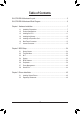
Table of Contents GA-Q77M-D2H Motherboard Layout................................................................................5 GA-Q77M-D2H Motherboard Block Diagram...................................................................6 Chapter 1 Hardware Installation......................................................................................7 1-1 1-2 1-3 1-4 1-5 1-6 1-7 Installation Precautions.....................................................................................
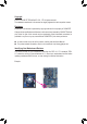
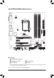
DDR3_1 DDR3_3 KB_MS DDR3_2 DDR3_4 GA-Q77M-D2H Motherboard Layout VGA_DVI ATX_12V ATX LGA1155 DP_HDMI_SPDIF SYS_FAN R_USB PCIEX16 Intel GbE LAN F_USB30 CPU_FAN GA-Q77M-D2H PCIEX1 BIOS Intel® Q77 PCI SATA3 0 1 PCIEX4 TPM IC (Note) BAT iTE Super I/O AUDIO LPT USB30_LAN SATA2 CODEC 2 3 4 5 DEBUG_PORT F_AUDIO F_USB2 SPDIF_O F_USB1 F_PANEL CLR_CMOS COMA COMB Box Contents GA-Q77M-D2H motherboard Motherboard driver disk Two SATA cables User's Manual I/O Shiel
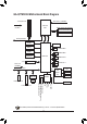
GA-Q77M-D2H Motherboard Block Diagram CPU CLK+/- (100 MHz) 1 PCI Express x16 LGA1155 CPU x16 PCI Express Bus DDR3 1600/1333/1066 MHz Dual Channel Memory FDI DMI 2.0 PCIe CLK (100 MHz) D-Sub BIOS DVI-D 2 SATA 6Gb/s HDMI 4 SATA 3Gb/s DisplayPort 4 USB 3.0/2.0 1 PCI 8 USB 2.0/1.
Chapter 1 Hardware Installation 1-1 Installation Precautions The motherboard contains numerous delicate electronic circuits and components which can become damaged as a result of electrostatic discharge (ESD). Prior to installation, carefully read the user's manual and follow these procedures: •• Prior to installation, make sure the chassis is suitable for the motherboard. •• Prior to installation, do not remove or break motherboard S/N (Serial Number) sticker or warranty sticker provided by your dealer.
1-2 Product Specifications CPU Support for Intel® Core™ i7 processors/Intel® Core™ i5 processors/ Intel® Core™ i3 processors/Intel® Pentium® processors/Intel® Celeron® processors in the LGA1155 package (Go to GIGABYTE's website for the latest CPU support list.) L3 cache varies with CPU Chipset Intel® Q77 Express Chipset Memory 4 x 1.
Storage Interface Chipset: - 2 x SATA 6Gb/s connectors (SATA3 0/1) supporting up to 2 SATA 6Gb/s devices - 4 x SATA 3Gb/s connectors (SATA2 2/3/4/5) supporting up to 4 SATA 3Gb/s devices - Support for RAID 0, RAID 1, RAID 5, and RAID 10 * When a RAID set is built across the SATA 6Gb/s and SATA 3Gb/s channels, the system performance of the RAID set may vary depending on the devices being connected. USB Chipset: - Up to 8 USB 2.0/1.
Hardware Monitor BIOS System voltage detection CPU/System temperature detection CPU/System fan speed detection CPU overheating warning CPU/System fan fail warning CPU/System fan speed control * Whether the CPU/system fan speed control function is supported will depend on the CPU/system cooler you install. Unique Features 1 x 64 Mbit flash Use of licensed AMI EFI BIOS PnP 1.0a, DMI 2.0, SM BIOS 2.6, ACPI 2.
1-3 Installing the CPU Read the following guidelines before you begin to install the CPU: •• Make sure that the motherboard supports the CPU. (Go to GIGABYTE's website for the latest CPU support list.) •• Always turn off the computer and unplug the power cord from the power outlet before installing the CPU to prevent hardware damage. •• Locate the pin one of the CPU. The CPU cannot be inserted if oriented incorrectly.
1-4 Installing the Memory Read the following guidelines before you begin to install the memory: •• Make sure that the motherboard supports the memory. It is recommended that memory of the same capacity, brand, speed, and chips be used. (Go to GIGABYTE's website for the latest supported memory speeds and memory modules.) •• Always turn off the computer and unplug the power cord from the power outlet before installing the memory to prevent hardware damage. •• Memory modules have a foolproof design.
1-6 Back Panel Connectors PS/2 Keyboard and PS/2 Mouse Port Use the upper port (green) to connect a PS/2 mouse and the lower port (purple) to connect a PS/2 keyboard. D-Sub Port The D-Sub port supports a 15-pin D-Sub connector. Connect a monitor that supports D-Sub connection to this port. DVI-D Port (Note) The DVI-D port conforms to the DVI-D specification and supports a maximum resolution of 1920x1200 (the actual resolutions supported depend on the monitor being used).
DisplayPort DisplayPort is one of the new generation interface technologies that delivers high quality digital imaging and audio, supporting bi-directional audio transmition. DisplayPort can support both DPCP and HDCP content protection mechanisms. Connect the audio/video device that supports DisplayPort to this port. The DisplayPort Technology can support a maximum resolution of 2560x1600 but the actual resolutions supported depend on the monitor being used.
1-7 Internal Connectors 1 2 4 14 5 11 3 6 7 9 10 1) ATX_12V 2) 3) 15 12 16 8 13 9) F_AUDIO ATX 10) SPDIF_O CPU_FAN 11) F_USB30 4) SYS_FAN 12) F_USB1/2 5) BAT 13) COMA/COMB 6) SATA3 0/1 14) LPT 7) SATA2 2/3/4/5 15) DEBUG_PORT 8) F_PANEL 16) CLR_CMOS Read the following guidelines before connecting external devices: •• First make sure your devices are compliant with the connectors you wish to connect.
1/2) ATX_12V/ATX (2x2 12V Power Connector and 2x12 Main Power Connector) With the use of the power connector, the power supply can supply enough stable power to all the components on the motherboard. Before connecting the power connector, first make sure the power supply is turned off and all devices are properly installed. The power connector possesses a foolproof design. Connect the power supply cable to the power connector in the correct orientation.
3/4) CPU_FAN/SYS_FAN (Fan Headers) All fan headers on this motherboard are 4-pin. Most fan headers possess a foolproof insertion design. When connecting a fan cable, be sure to connect it in the correct orientation (the black connector wire is the ground wire). The speed control function requires the use of a fan with fan speed control design. For optimum heat dissipation, it is recommended that a system fan be installed inside the chassis. CPU_FAN: 1 CPU_FAN 1 SYS_FAN Pin No.
DEBUG PORT DEBUG PORT 6) SATA3 0/1 (SATA 6Gb/s Connectors, Controlled by Intel Q77 Chipset) The SATA connectors conform to SATA 6Gb/s standard and are compatible with SATA 3Gb/s and SATA 1.5Gb/s standard. Each SATA connector supports a single SATA device. The "SATA3 0" and "SATA3 1" connectors support RAID 0 and RAID 1. RAID 5 and RAID 10 can be implemented on the two connectors with the "SATA2 2/3/4/5" connectors (Note). Pin No.
8) F_PANEL (Front Panel Header) Connect the power switch, reset switch, speaker, chassis intrusion switch/sensor and system status indicator on the chassis to this header according to the pin assignments below. Note the positive and negative pins before connecting the cables.
9) F_AUDIO (Front Panel Audio Header) The front panel audio header supports Intel High Definition audio (HD) and AC'97 audio. You may connect your chassis front panel audio module to this header. Make sure the wire assignments of the module connector match the pin assignments of the motherboard header. Incorrect connection between the module connector and the motherboard header will make the device unable to work or even damage it. 9 For HD Front Panel Audio: Pin No.
The header conforms to USB 3.0/2.0 specification and can provide two USB ports. For purchasing the optional 3.5" front panel that provides two USB 3.0/2.0 ports, please contact the local dealer. TPM w/housing DIP DIP 1 2 3 1 2 3 PCIe power connector (SATA)(X58A-OC) 11) F_USB30 (USB 3.0/2.0 Header) DIP 1 2 3 DIP 1 2 3 PWM Switch (X58A-OC) Voltage measurement module(X58A-OC) 1 M_S 1 10 11 1 20 1 1 DB_PORT BIOS Switcher (X58A-OC) Definition VBUS SSRX1SSRX1+ GND SSTX1G.
G.QBOFM 13) COMA/COMB (Serial Port Headers) The COM header can provide one serial port via an optional COM port cable. For purchasing the optional COM port cable, please contact the local dealer. 9 10 1 2 Pin No. 1 2 3 4 5 6 7 8 9 10 Definition NDCDNSIN NSOUT NDTRGND NDSRNRTSNCTSNRINo Pin 14) LPT (Parallel Port Header) The LPT header can provide one parallel port via an optional LPT port cable. For purchasing the optional LPT port cable, please contact the local dealer.
15) DEBUG PORT (Debug Card Header) (Note) This header can connect a debug card. 11 1 12 2 Pin No. 1 2 3 4 5 6 7 8 9 10 11 12 Definition No Pin GND VCC3 LAD0 LAD1 LAD2 LAD3 -LFRAME -PFMRST DB CLK DB_P_SENSOR NC 16) CLR_CMOS (Clear CMOS Jumper) Use this jumper to clear the CMOS values (e.g. date information and BIOS configurations) and reset the CMOS values to factory defaults. To clear the CMOS values, use a metal object like a screwdriver to touch the two pins for a few seconds.
Chapter 2 BIOS Setup BIOS (Basic Input and Output System) records hardware parameters of the system in the CMOS on the motherboard. Its major functions include conducting the Power-On Self-Test (POST) during system startup, saving system parameters and loading operating system, etc. BIOS includes a BIOS Setup program that allows the user to modify basic system configuration settings or to activate certain system features.
2-2 The Main Menu On the main menu of the BIOS Setup program, press arrow keys to move among the items and press to accept or enter a sub-menu. Or you can use your mouse to select the item you want. (Sample BIOS Version: E18c) Setup Menus Help Function Keys Configuration Items Current Settings BIOS Setup Menus M.I.T. Use this menu to configure the clock, frequency, and voltages of your CPU and memory, etc. Or check the system/CPU temperatures, voltages, and fan speeds.
2-3 M.I.T. Whether the system will work stably with the overclock/overvoltage settings you made is dependent on your overall system configurations. Incorrectly doing overclock/overvoltage may result in damage to CPU, chipset, or memory and reduce the useful life of these components. This page is for advanced users only and we recommend you not to alter the default settings to prevent system instability or other unexpected results. (Inadequately altering the settings may result in system's failure to boot.
`` M.I.T. Current Status This screen provides information on CPU/memory frequencies/parameters. `` Advanced Frequency Settings && Processor Graphics Clock Allows you to set the onboard graphics clock. The adjustable range is from 400 MHz to 3200 MHz. (Default: Auto) && CPU Clock Ratio Allows you to alter the clock ratio for the installed CPU. The adjustable range is dependent on the CPU being installed. && CPU Frequency Displays the current operating CPU frequency.
&& CPU Clock Ratio, CPU Frequency The settings under the two items above are synchronous to those under the same items on the Advanced Frequency Settings menu. && Intel(R) Turbo Boost Technology (Note) Allows you to determine whether to enable the Intel CPU Turbo Boost technology. Auto lets the BIOS automatically configure this setting. (Default: Auto) && Turbo Ratio (1-Core Active~4-Core Active) (Note) Allows you to set the CPU Turbo ratios for different number of active cores.
&& Extreme Memory Profile (X.M.P.) (Note) Allows the BIOS to read the SPD data on XMP memory module(s) to enhance memory performance when enabled. Disabled Disables this function. (Default) Profile1 Uses Profile 1 settings. (Note 2) Profile2 Uses Profile 2 settings. && System Memory Multiplier (SPD) Allows you to set the system memory multiplier. Auto sets memory multiplier according to memory SPD data.
&& DRAM Timing Selectable Quick and Expert allows the Channel Interleaving, Rank Interleaving, and memory timing settings below to be configurable. Options are: Auto (default), Quick, Expert. && Profile DDR Voltage When using a non-XMP memory module or Extreme Memory Profile (X.M.P.) is set to Disabled, this item will display as 1.50V. When Extreme Memory Profile (X.M.P.) is set to Profile1 or Profile2, this item will display the value based on the SPD data on the XMP memory.
`` PC Health Status && Reset Case Open Status Disabled Keeps or clears the record of previous chassis intrusion status. (Default) Enabled Clears the record of previous chassis intrusion status and the Case Open field will show "No" at next boot. && Case Open Displays the detection status of the chassis intrusion detection device attached to the motherboard CI header. If the system chassis cover is removed, this field will show "Yes", otherwise it will show "No".
&& Slope PWM Allows you to control the CPU fan speed. This item is configurable only when CPU Fan Speed Control is set to Manual. Options are: 0.75 PWM value /oC ~ 2.50 PWM value /oC. && System Fan Speed Control Allows you to determine whether to enable the system fan speed control function and adjust the fan speed. Normal Allows the system fan to run at different speeds according to the system temperature. (Default) Silent Allows the system fan to run at slow speeds.
2-4 System This section provides information on your CPU, memory, motherboard model, and BIOS version. You can also select the default language used by the BIOS and manually set the system time. && System Language Selects the default language used by the BIOS. && System Date Sets the system date. The date format is week (read-only), month, date, and year. Use to switch between the Month, Date, and Year fields and use the <+> or <-> key to set the desired value.
2-5 BIOS Features && Boot Option Priorities Specifies the overall boot order from the available devices. For example, you can set hard drive as the first priority (Boot Option #1) and DVD ROM drive as the second priority (Boot Option #2). The list only displays the device with the highest priority for a specific type. For example, only hard drive defined as the first priority on the Hard Drive BBS Priorities submenu will be presented here.
&& Limit CPUID Maximum (Note) Allows you to determine whether to limit CPUID maximum value. Set this item to Disabled for Windows XP operating system; set this item to Enabled for legacy operating system such as Windows NT4.0. (Default: Disabled) && Execute Disable Bit (Note) Enables or disables Intel Execute Disable Bit function.
2-6 Peripherals && LAN PXE Boot Option ROM Allows you to decide whether to activate the boot ROM integrated with the onboard LAN chip. (Default: Disabled) && SATA Controller(s) Enables or disables the integrated SATA controllers.
&& SATA Mode Selection Enables or disables RAID for the SATA controllers integrated in the Intel Chipset or configures the SATA controllers to AHCI mode. IDE Configures the SATA controller to IDE mode. (Default) AHCI Configures the SATA controller to AHCI mode. Advanced Host Controller Interface (AHCI) is an interface specification that allows the storage driver to enable advanced Serial ATA features such as Native Command Queuing and hot plug.
&& Audio Controller Enables or disables the onboard audio function. (Default: Enabled) If you wish to install a 3rd party add-in audio card instead of using the onboard audio, set this item to Disabled. && PCH LAN Controller Enables or disables the onboard LAN function. (Default: Enabled) If you wish to install a 3rd party add-in network card instead of using the onboard LAN, set this item to Disabled.
`` Intel TXT(LT) Configuration Enables or disables Intel Trusted Execution Technology (Intel TXT). Intel Trusted Execution Technology provides a hardware-based security foundation. By isolating assigned memory through this hardwarebased protection, it allows the system to protect data in each virtual partition from unauthorized access from software in another partition.
`` Intel Anti-Theft Technology Configuration This section allows you to enable/disable Intel Anti-Theft Technology (Intel AT), a hardware-based anti-theft protection solution, and provides you with related configuration options. `` AMT Configuration This section allows you to enable/disable Intel Active Management Technology (Intel AMT) for remote computer management on hardware level and provides you with further configuration options.
&& Parallel Port Enables or disables the onboard parallel port. (Default: Enabled) `` Intel(R) Smart Connect Technology && ISCT Configuration Enables or disables Intel Smart Connect Technology. (Default: Disabled) `` Serial Port Console Redirection This section allows you to enable/disable serial port console redirection for remote server management through a serial port.
2-7 Power Management && AC BACK Determines the state of the system after the return of power from an AC power loss. Always Off The system stays off upon the return of the AC power. (Default) Always On The system is turned on upon the return of the AC power. Memory The system returns to its last known awake state upon the return of the AC power. && Power On By Keyboard Allows the system to be turned on by a PS/2 keyboard wake-up event.
&& High Precision Event Timer (Note) Enables or disables High Precision Event Timer (HPET) for Windows 7 operating system. (Default: Enabled) && Soft-Off by PWR-BTTN Configures the way to turn off the computer in MS-DOS mode using the power button. Instant-Off Press the power button and then the system will be turned off instantly. (Default) Delay 4 Sec Press and hold the power button for 4 seconds to turn off the system.
2-8 Save & Exit && Save & Exit Setup Press on this item and select Yes. This saves the changes to the CMOS and exits the BIOS Setup program. Select No or press to return to the BIOS Setup Main Menu. && Exit Without Saving Press on this item and select Yes. This exits the BIOS Setup without saving the changes made in BIOS Setup to the CMOS. Select No or press to return to the BIOS Setup Main Menu.
Chapter 3 Drivers Installation •• Before installing the drivers, first install the operating system. •• After installing the operating system, insert the motherboard driver disk into your optical drive. The driver Autorun screen is automatically displayed which looks like that shown in the screen shot below. (If the driver Autorun screen does not appear automatically, go to My Computer, double-click the optical drive and execute the Run.exe program.
3-2 Regulatory Statements Regulatory Notices This document must not be copied without our written permission, and the contents there of must not be imparted to a third party nor be used for any unauthorized purpose. Contravention will be prosecuted. We believe that the information contained herein was accurate in all respects at the time of printing. GIGABYTE cannot, however, assume any responsibility for errors or omissions in this text.
- 47 -
- 48 -
- 49 -
- 50 -
- 51 -
Contact Us GIGA-BYTE TECHNOLOGY CO., LTD. Address: No.6, Bau Chiang Road, Hsin-Tien, Taipei 231, Taiwan TEL: +886-2-8912-4000, FAX: +886-2-8912-4003 Tech. and Non-Tech. Support (Sales/Marketing) : http://ggts.gigabyte.com.tw WEB address (English): http://www.gigabyte.com WEB address (Chinese): http://www.gigabyte.tw You may go to the GIGABYTE website, select your language in the language list on the top right corner of the website.