Poseidon 310 English User’s Manual GZ-AA3CB-SJS / SJB
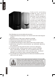
English Thank you for purchasing G I G A B Y T E Te c h . t h e r m a l produc t. GIGABY TE Tech. is dedicated to the integration of casing water/air- cooling solution technology to provide users with the most optimal solution for thermal dissipation. For fur ther information and specifications of the “Poseidon” series, please visit GIGABYTE Tech. website. (http://www.gigabyte.com.tw) The following are not covered by the warranty: 1.
English Table of Contents 1. Components Introduction 3 1-1 Casing’s Internal Structure 4 1-2 Front, Rear, and Left Side Panel Structure 5 1.3 Removal of Side and Front Panel 5 2. Features 6 3. Specifications 7 4.
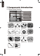
English 1.Components Introduction 1-1 Casing’s Internal Structure Power Supply Bay PCI Tool-Free Fastener 5.25” Front Device Bay Motherboard tray 3.5” Front Device Bay 3.
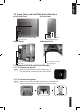
English 1-2 Front, Rear, and Left Side Panel Structure a) Left Side Panel Ventilated Mesh Side Panel Kit Left Side Panel c) Rear Panel LCS Tube Outlets Rear Fan b) Front Panel Power Switch and Front Multi-Media I/O port d) Bottom Panel Removable / washable air-intake filter 1-3 Removal of Side and Front Panels 1-3.1 To remove side panels: 1-3.1a Remove the 4 thumb screws at the rear of the side panel, and detach the side panels. 1-3.2 To remove front panel: 1-3.
English 2.Feature -High Quality Design Innovative sleek dual-tone design coupled with sophisticated yet simple, precise workmanship. Illuminated and atmospherically-soothing backlight for a post-modern classy impression. Removable / washable air-intake filter. -Complete Support Complete front panel multi-media support, include 2 x USB 2.0, 1 x IEEE1394, 1 x audio set (HD & AC97) Full Support of Gigabyte Tech.
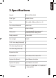
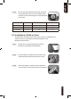
English 3.Specifications Model GZ-AA3CB-SJS/SJB Case Type Middle Tower Size 200 x 440 x 505mm (W x H x D) Front Bezel Material Aluminum Color Silver or Black Side panel Interchangeable transparent / ventilated-mesh side panel Body material 0.7mm SECC Net weight 8.8 KG 5.25” drive bay (External) 5 3.5 drive bay (External) 2 3.
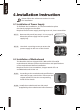
English 4.Installation Instruction Please follow the reference sections in order for installation 4-1 Installation of Power Supply To facilitate the installation, it is recommended to place the chassis upright on the table. Required Tools: Power supply securing screw x 4; Cross screwdriver. 4-1.1 Remove side panel (see step 1-3.1 on page 5). Place the power supply into the power supply bay. 4-1.2 Use the 4 x securing screws to secure the power supply to the rear of the chassis.
English 4-2.3 Secure the motherboard with the securing screws (Please refer to your motherboard manual to check what type of motherboard you have). Motherboard Code name Motherboard screws Case copper post ATX A1-A9 9 9 Micro ATX U1-U9 9 9 Flex ATX F1-F6 6 6 4-3 Installation of Add-on Card The Poseidon 310 does not require any tools for installation of add-on cards, e.g. Graphics card and network card. Required Tools: None 4-3.
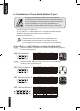
English 4-4 Installation of Front Multi-Media I/O port Incorrect connection of the slots can cause the motherboard to malfunction or completely destroy the motherboard. Please read the manual carefully in the installation as incorrect installations or connection causing faults will void your warranty. The front panel consists of: (1) 2 x USB 2.0, 1 x IEEE 1394 and 1 x Audio Set (HD & AC’97) (2) Basic casing power switch control cable kit.
English 4-4.3 Insert the Audio connector into the corresponding socket on the motherboard. HD AUDIO AC'97 Pin 1 2 3 4 5 Definition MIC2_L GND MIC2_R -ACZ_DET LINE2_R Pin 6 7 8 9 10 Definition FSENSE1 FAUDIO_JD Pin 1 2 3 4 5 Definition MIC GND MIC Power NC Line Out(R) Pin 6 7 8 9 10 Definition NC NC LINE2_L FSENSE2 Line Out(L) NC (2) Basic casing power switch control cable kit.
English 4-6 Installation of 5.25” Front Device Bay 4-6.1 Detach the front panel (see step 1-3.2 on page 5) and remove the mesh drive rail from the front panel. 4-6.2 Remove the front EMI plate and attach the front panel onto the chassis. 4-6.3 Slide the 5.25” device into the drive bay from the front of the chassis. 4-6.4 Secure the 5.25” device with the internal latch. Refer to the figure for installation procedure. Lock 4-7 Installation of 3.5” Front Device Bay Installation of 3.
English 4-8.1 Fit the securing runners on both sides of the HDD and slide the HDD into the internal drive bay. Additional HDD can be installed in the 3.5” front device bay. Slide in the HDD and lock the internal latch to secure the HDD. 4-9 Foot Supports The Poseidon 310 is supplied with four high-end skid-proof foot supports for ensuring the casing is firmly seated on the holding surface.
English 4-11 Recommended Cooling Products The Poseidon 310 is recommended to be used with GIGABYTE Cooling products.