
User`s manual

10
English
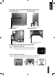
4-4 Installation of Front Multi-Media I/O port
Incorrect connection of the slots can cause the
motherboard to malfunction or completely destroy
the motherboard. Please read the manual carefully
in the installation as incorrect installations or
connection causing faults will void your warranty.
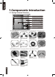
The front panel consists of:
(1) 2 x USB 2.0, 1 x IEEE 1394 and 1 x Audio Set (HD & AC’97)
(2) Basic casing power switch control cable kit.
Required Tools: None
(1) 2 x USB 2.0, 1 x IEEE 1394 and 1 x Audio Set (HD & AC’97)
4-4.1 Insert the USB 2.0 connectors into the corresponding socket
on the motherboard.
4-4.2 Insert the IEEE 1394 connector into the corresponding
socket on the motherboard.
Please refer to the instructions supplied by the
motherboard manufacturer and make sure the
correct type of connector is used prior to installation.
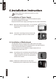
Pin Definition Pin Definition
1 Power 6 USB Dy+
2 Power 7 GND
3 USB Dx- 8 GND
4 USB Dy- 9
5 USB Dx+ 10 USB Over current
USB 2.0 connector
Pin Definition Pin Definition
1 TPA+ 6 TPB-
2 TPA- 7
3 GND 8 +12V
4 GND 9 +12V
5 TPB+ 10 GND
IEEE 1394 connector A
Pin Definition Pin Definition
1 TPA+ 6 TPB-
2 TPA- 7 +12V
3 GND 8 +12V
4 GND 9
5 TPB+ 10 GND
IEEE 1394 connector B
Pin Definition Pin Definition
1 +12V 9 +12V
2 +12V 10 +12V
3 TPA+ 11 TPA1+
4 TPA- 12 TPA1-
5 GND 13 GND
6 GND 14
7 TPB+ 15 TPB1+
8 TPB- 16 TPB1-
IEEE 1394 connector C
A
B C