
User`s manual


English
11
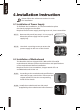
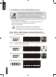
4-4.3 Insert the Audio connector into the corresponding socket on
the motherboard.
(2) Basic casing power switch control cable kit.
Follow the connectors list below for installation (see figure below)
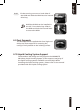
Different motherboards have different
installation areas and specifications, screw holes
and connectors. For detailed instructions, please
refer to the motherboard user manual supplied
by the motherboard manufacturer.
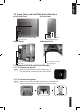
4-5 Connection of Fan Power Cables
The Poseidon 310 has one 12cm silent cooling fan in the front and
one in the rear. This case includes internal connectors that connects
the front and rear fans making it a single 3-pin connector.
Required Tools: None
4-5.1 Plug the 3-pin connector into the
corresponding system fan socket on the
motherboard.
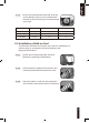
Pin Definition Pin Definition
1 MIC2_L 6 FSENSE1
2 GND 7 FAUDIO_JD
3 MIC2_R 8
4 -ACZ_DET 9 LINE2_L
5 LINE2_R 10 FSENSE2
HD AUDIO
Pin Definition Pin Definition
1 MIC 6 NC
2 GND 7 NC
3 MIC Power 8
4 NC 9 Line Out(L)
5 Line Out(R) 10 NC
AC'97
Connector Color
Speaker Yellow(+) / Black(-)
Power SW Orange(+) / White(-)
HDD LED Red(+) / White(-)