GA-8ILFT Series P4 Titan-DDR Motherboard USER’S MANUAL Pentium® 4 Processor Motherboard Rev.
English Table of Content Item Checklist ..................................................................................4 WARNING! .......................................................................................4 Chapter 1 Introduction .......................................................................5 Features Summary ................................................................................................ 5 GA-8ILFT Series Motherboard Layout ..........................................
E Power Management Setup ................................................................................ 35 PnP/PCI Configurations ...................................................................................... 37 PC Health Status .................................................................................................. 38 Frequency/Voltage Control ................................................................................ 40 Load Fail-Safe Defaults .....................................
English Item Checklist þ þ þ þ The GA-8ILFT motherboard IDE cable x 1/ Floppy cable x 1 CD for motherboard driver & utility (IUCD) GA-8ILFT user’s manual þ I/O Shield WARNING! Computer motherboards and expansion cards contain very delicat e Integrated Circuit (IC) chips. To protect them against damage from static electricity, you should follow some precautions whenever you work on your computer. 1. Unplug your computer when working on the inside. 2.
E Chapter 1 Introduction Features Summary — — CP U — 20.3cm x 2.9cm Flex ATX size form factor, 4 layers PCB. GA-8ILFT Series Motherboard: GA-8ILFT and GA-8ILFT-C Socket 478 for Intel® Micro FC-PGA2 Pentium® 4 processor — Support Intel® Pentium® 4 (Northwood, 0.
English On-Board LAN* Hardware Monitor PS/2 Connector BIOS Additional Features — — — — — — — — — — — — — — — — Builit in RTL8100BL Chipset 1 RJ45 port CPU/System Fan Revolution detect CPU/System Fan Control CPU O verheat Warning System Voltage Detect PS/2 Keyboard interface and PS/2 Mouse interace Licensed AWARD B IOS, 2M bit FWH External Modem wake up PS/2 Keyboard password power on PS/2 Mouse power on AC Recovery USB KB/ Mouse wake up from S3 Poly fuse for keyboard,USB,game port over-current protectio
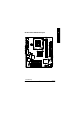
CPU_FAN COMA ATX_12V LPT VGA ATX_POWER KB_MS FDD DDR2 DDR1 E GA-8ILFT Series Motherboard Layout IDE1 IDE2 F_AUDIO Intel 845GL GAME MIC_IN LINE_OUT LINE_IN SOCKET478 GA-8ILFT BAT1 RTL8100BL* CI S_IRG CD_IN PCI1 F_USB1 AUX_IN PCI3 BIOS F_PANEL PCI2 BIOS_WP AC97 Buzzer ICH4 CLR_COMS ITE8712 SYS _FAN USB/ LAN* SPDIF n * For GA-8ILFT Only.
English Chapter 2 Hardware Installation Process To set up your computer, you must complete the following steps: Step 1- Install the Central Processing Unit (CPU) Step 2- Install memory modules Step 3- Connect ribbon cables, cabinet wires, and power supply Step 4- Setup BIOS software Step 5- Install supporting software tools Step1 Step4 Step 2 Step 4 Step 4 Step3 GA-8ILFT Series Motherboard -8-
E Step 1: Install the Central Processing Unit (CPU) Step 1-1 : CPU Installation Pin1 indicator Pin1 indicator CPU Top V iew CPU Bott om View Socket Actuation Lever 1. Pull up the CP U socket lever and up to 90-degree angle. 3. Press down the CPU socket lever and finish CPU installation. Pin1 indicator 2. Locate Pin 1 in the socket and look for a (golden) cut edge on the CPU upper corner. Then insert the CPU into the socket. M Please make sure the CPU type is supported by the motherboard.
English Step 1-2 : CPU Heat Sink Installation 2. Hook the other end of the cooler bracket to the CPU socket. 1. Hook one end of the cooler bracket to the CPU socket first. M Please use Intel ap proved cooling fan. M We recommend you to apply the thermal tape to provide better heat conduction between your CPU and heatsink. (The CPU cooling fan might stick to the CPU due to the hardening of the thermal paste.
E Step 2: Install memory modules The motherboard has 2 dual inline memory module (DIMM) sockets. The BIOS will automatically detects memory type and size. To install the memory module, just push it vertically into the DIMM Slot .The DIMM module can only fit in one direct ion due to the notch. Memory size can vary bet ween sockets.
English DDR Introduction Established on the existing SDRAM industry infrastructure, DDR (Double Data Rate) memory is a high performance and cost-effective solution that allows easy adoption for memory vendors, OEMs and system integrators. DDR memory is a sensible evolutionary solution for the PC industry t hat builds on the existing SDRAM infrastructure, yet makes awesome advances in solving the system performance bottleneck by doubling t he memory bandwidth.
E Step 3: Connect ribbon cables, cabinet wires, and power supply Step3-1 : I/O Back Panel Introduction v u w y* x u PS/2 Keyboard and PS/2 Mouse Connector PS/2 Mouse Connector (6 pin Female) ØThis connector supports standard PS/2 keyboard and PS/2 mouse. PS/2 Keyboard Connector (6 pin Female) v Parallel Port and Serial Ports (COM1/COM2) Parallel Port (25 pin Female) ØThis connector supports 2 standard COM ports and 1 Parallel port.
English w Game /MIDI Ports ØThis connector supports joystick, MIDI keyboard and other relate audio devices. Joystick/ MIDI (15 pin Female) x Audio Connectors Ø After install onboard audio driver, you may connect speaker to Line Out jack, micro phone to MIC In jack. Device like CD-ROM , walkman etc can be connected to Line-In jack.
A E Step 3-2 : Connectors Introduction B C D E Q P O F G N H I M L K J A) ATX_12V J) BIOS_WP B) CPU_FAN K) F_U SB1 C) ATX L) BATTERY D) FDD M) AUX_IN E) IDE1/ID E2 N) CD_IN F) SYS_FAN O) S_IR Q G) C I P) SPDIF H) CLR_CMOS Q) F_AUDIO I) F_PANEL n * For GA-8ILFT Only.
3 4 +12V GND +12V GND ØThis connector (ATX +12V) suppliesthe CPU operation voltage (Vcore). If this " ATX+ 12V connector" is not connected, system cannot boot. 1 2 B) CPU_FAN (CPU FAN Connector) Ø Please note, a proper installation of the CPU cooler is essential to prevent the CPU from running under abnormal condition or damaged by overheating.The CPU fan connector Sense +12V/Control GND English A) ATX_12V ( +12V Power Connector) supports Max. current up to 600 mA.
E D) FDD (Floppy Connector) 1 E) IDE1/ IDE2 (IDE1/IDE2 Conn ector) 1 IDE2 IDE1 1 Ø Important Notice: Please connect first harddisk to IDE1 and connect CDROM to IDE2. USB Over Current Power USB DyUSB Dy+ GND K) F_USB 1 (Front USB Co nnector) Ø Be careful with the polarity of the front panel USB connector. Check the pin assignment while you connect the front panel USB cable. Please contact your nearest dealer for optional front panel USB cable.
English N) CD_IN (CD IN) 1 CD-L GND CD-R CD_I N Q)F_AUDIO (F_AUDIO Connector) MI C REF Front Audio (R) Reserved Front Audio (L) Ø If you want to use Front Audio connector, you must remove 5-6, 9-10 Jumper. In order to utilize the front audio header, your chassis must have front audio connector. Also please make sure the pin assigment on the cable is the GND POWER same as the pin assigment on the MB header.
1 3.3V -12V GND PS-ON(SoftOn/Off) GND GND GND -5V V CC V CC 20 ØAC power cord should only be connected to E C) ATX_POWER (ATX Power) your power supply unit after ATX power cable and other related devices are firmly 3.3V 3.3V connected to the mainboard. GND V CC GND V CC GND Power Good 5V SB (Stand by +5V) +12V J) B IOS_WP (BIOS Write Protect ion) Ø Please note, To flash/upgrade BIOS on this MB BIOS_WP must be set to 2-3 close.
1 AUX-L GND AUX-R English M) AUX_IN ( AUX In Connector) H) CLR _CMOS (Clear CMOS) Ø You may clear the CMOS data to its default values by this jumper. 2-3 close: Normal 1 1-2 close: Clear CMOS 1 L) BATTERY (Battery) + GA-8ILFT Series Motherboard CAUTION v Danger of explosion if battery is incorrectly replaced. v Replace only with the same or equivalent type recommended by the manufacturer. v Dispose of used batteries according to the manufacturer’s instructions.
13 14 E I) F_PANEL (2x7 pins connector) RSTRST+ SPK+ 1 PW+ PWPD+ PD_GPD_Y- SPK2 HD (IDE Hard Disk Active LED) SPK (Speaker Connector) RST (Reset Switch) PD+/PD_G-/PD_Y-(Power LED) PW (Soft Power Connector) 1 1 HD+ HD- Pin 1: LED anode(+) Pin 2: LED cathode(-) Pin 1: VCC(+) Pin 2- P in 3: NC Pin 4: Data(-) Open: Normal Operation Close: Reset Hardware System Pin 1: LED anode(+) Pin 2: LED cathode(-) Pin 3: LED cathode(-) Open: Normal Operation Close: Power On/Off Ø Please connect the power LED, PC
English Chapter 3 BIOS Setup BIOS Setup is an overview of the BIOS Setup Program. The program that allows users to modify the basic system configuration. This type of information is stored in battery-backed CMOS RAM so that it retains the Setup information when the power is turned off. ENTERING SETUP Powering ON the computer and pressing immediately will allow you to enter Setup. If you require more advanced BIOS settings, please go to “Advanced BIOS” setting menu.
E GETTING HELP Main Menu The on-line description of the highlighted setup function is displayed at the bottom of the screen. Status Page Setup Menu / Option Page Setup Menu Press F1 to pop up a small help window that describes the appropriate keys to use and the possible selections for the highlighted item. To exit the Help Window press . The Main Menu (For example: BIOS Ver. : F1) Once you enter Award BIOS CMOS Setup Utility, the Main Menu (Figure 1) will appear on the screen.
English l IntegratedPeripherals This setup page includes all onboard peripherals. l PowerManagement Setup This setup page includes all the items of Green function features. l PnP/PCI Configurations This setup page includes all the configurations of PCI & PnP ISA resources. l PC Health Status This setup page is the System auto detect Temperature, voltage, fan, speed. l Frequency/Voltage Control This setup page is control CPU’s clock and frequency ratio.
E Standard CMOS Features CMOS Setup Utility-Copyright (C) 1984-2002 Award Software Standard CMOS Features Date (mm:dd:yy) Mon, Feb 21 2000 Item Help Time (hh:mm:ss) 22:31:24 Menu Level u Change the day, month, }IDE Primary Master None }IDE Primary Slave None year }IDE Secondary Master None }IDE Secondary Slave None Sun. to Sat. Drive A 1.44M, 3.5 in. Drive B None Jan. to Dec.
English C Time The times format in . The time is calculated base on the 24-hour militarytime clock. For example, 1 p.m. is 13:00:00. C IDE Primary Master, Slave / IDE Secondary Master, Slave The category identifies the types of hard disk from drive C to F that has been installed in the computer. There are two types: auto type, and manual type. Manual type is user-definable; Auto type which will automatically detect HDD type.
8Disabled Normal Floppy Drive. (Default value) 8Drive A Drive A is 3 mode Floppy Drive. 8Drive B Drive B is 3 mode Floppy Drive. 8Both Drive A & B are 3 m ode Floppy Drives. E C Floppy 3 Mode Support (for Japan Area) C Halton The category determines whether the computer will stop if an error is detected during power up. 8NO Errors The system boot will not stop for any error that may be detected and you will be prompted.
English Advanced BIOS Features CMOS Setup Utility-Copyright (C) 1984-2002 Award Software Advanced BIOS Features First Boot Device Floppy Item Help Second Boot Device HDD-0 Menu Level u Third Boot Device CDROM Boot Up Floppy Seek Disabled Init Display First Onboard/AGP Graphics Aperture Size 128MB Graphics Share Memory 8MB higf: Move Enter:Select +/-/PU/PD:Value F10:Save ESC:Exit F5:Previous Values F6:Fail-Safe Defaults Figure 3: Advanced BIOS Features C First / Second / Third Boot Device
E C Boot Up Floppy Seek During POST, BIOS will determine the floppy disk drive installed is 40 or 80 tracks. 360 K type is 40 tracks 720 K, 1.2 M and 1.44 M are all 80 tracks. 8Enabled BIOS searches for floppy disk drive to determine it is 40 or 80 tracks. Note that BIOS can not tell from 720 K, 1.2 M or 1.44 M drive type as they are all 80tracks. 8Disabled BIOS will not search for the type of floppy disk drive by track number.
English Integrated Peripherals CMOS Setup Utility-Copyright (C) 1984-2002 Award Software Integrated Peripherals On-Chip Prim ary PCI IDE Enabled Item Help On-Chip Secondary PCI IDE Enabled Menu Level u IDE1 Conductor Cable Auto If a hard disk IDE2 Conductor Cable Auto controller card is USB Controller Enabled used, set at Disable USB Keyboard Support Disabled USB Mouse Support Disabled [Enabled] AC97 Audio Auto Enable onboard IDE Onboard LAN Enabled Onboard LAN Boot ROM Disabled
E C On-Chip Secondary PCI IDE 8Enabled Enable onboard 2nd channel IDE port. (Default value) 8Disabled Disable onboard 2nd channel IDE port. C IDE1 Conductor Cable 8Auto Will be automatically detected by BIOS. (Default Value) 8ATA66/100 Set IDE1 Conductor Cable to ATA66/100 (Please make sure your IDE device and cable is compatible with ATA66/100). 8ATA33 Set IDE1 Conductor Cable to ATA33 (Please make sure your IDE devic e and cable is compatible with ATA33).
English C AC97 Audio 8Auto Enable onboard AC'97 audio function. (Default Value) 8Disabled Disable this function. C OnboardLAN 8Enabled Enabled Onboard LAN function. (Default value) 8Disabled Disabled onboard LAN function. C Onboard LAN Boot ROM 8Enabled Enabled Onboard LAN Boot ROM function. 8Disabled Disabled onboard LAN Boot ROM function.(Default value) C Onboard Serial Port 1 8Auto BIOS will automatically setup the port 1 address. 83F8/IRQ4 Enable onboard Serial port 1 and address is 3F8.
Set onboard I/O chip UART to ASKIR Mode. 8IrDA Set onboard I/O chip UART to IrDA Mode. 8Normal Set onboard I/O chip UART to Normal Mode. (Default Value) E 8ASKIR C UR2 Duplex Mode 8Half IR Function Duplex Half. (Default Value) 8Full IR Function Duplex Full. C OnboardParallel port 8378/IRQ7 Enable onboard LPT port and address is 378/IRQ7. (Default Value) 8278/IRQ5 Enable onboard LPT port and address is 278/IRQ5. 8Disabled Disable onboard LPT port.
English 8330 Set Midi Port Address to 330.(Default Value) 8Disabled Disable this function. C Midi Port IRQ 85 Set Midi Port IRQ to 5. 810 Set Midi Port IRQ to 10.
E Power Management Setup CMOS Setup Utility-Copyright (C) 1984-2002 Award Software Power Management Setup ACPI Suspend Type S1(POS) Item Help Soft-Off by PWR_BTTN Instant-Off Menu Level u PME Event Wake Up Enabled [S1] ModemRingOn/WakeOnLan Enabled Resume by Alarm Disabled Set suspend type to x Date (of Month) Alarm Ev eryday Power On Suspend under x Time (hh:nn:ss) 0 0 0 ACPI OS Power On By M ouse Disabled Power On By Key board Disabled [S3] x KB Power ON Password Enter Set susp
English C PME EventWake Up 8Disabled Disable this function. 8Enabled Enable PME Event Wake up. (Default Value) C ModemRingOn/WakeOnLAN 8Disabled Disable Modem Ring on/wake on Lan function. 8Enabled Enable Modem Ring on/wake on Lan. (Default Value) C Resume by Alarm You can set "Resume by Alarm" item to enabled and key in Data/tim e to power on system. 8Disabled Disable this function. (Default Value) 8Enabled Enable alarm function to POWER ON system. If RTC Alarm Lead To Power On is Enabled.
E PnP/PCI Configurations CMOS Setup Utility-Copyright (C) 1984-2002 Award Software PnP/PCI Configurations PCI 1 IRQ Assignment Auto Item Help PCI 2 IRQ Assignment Auto Menu Level u PCI 3 IRQ Assignment Auto higf: Move Enter:Select +/-/PU/PD:Value F10:Save ESC:Exit F5:Previous Values F6:Fail-Safe Defaults F1:General Help F7:Optimized Defaults Figure 6: PnP/PCI Configurations C PCI 1 IRQ Assignment 8Auto Auto assign IRQ to PCI.
English PC Health Status CMOS Setup Utility-Copyright (C) 1984-2002 Award Software PC Health Status Reset Case Open Status Disabled Item Help Case Opened No Menu Level u VCORE 1.730V +1.5V 1.502V +3.3V 3.360V +5V 5.053V +12V 11.
E C Current CPU Temperature 8Detect CPU Temp. automatically. C Current CPU/SYSTEM FAN Speed (RPM) 8Detect CPU/SYSTEM Fan speed status automatically. C CPU Warning Temperature 860°C / 140°F Monitor CPU Temp. at 60°C / 140°F. 870°C / 158°F Monitor CPU Temp. at 70°C / 158°F. 880°C / 176°F Monitor CPU Temp. at 80°C / 176°F. 890°C / 194°F Monitor CPU Temp. at 90°C / 194°F. 8Disabled Disable this function.(Default value) C CPU FAN Fail Warning 8Disabled Fan Warning Function Disable.
English Frequency/Voltage Control CMOS Setup Utility-Copyright (C) 1984-2002 Award Software Frequency/Voltage Control CPU Clock Ratio 15X Item Help CPU Host Clock Control Disabled Menu Level u x CPU Host Frequency (Mhz) 100 x PCI/AGP Divider Disabled Host/DRAM Clock ratio Auto Memory Frequency (Mhz) 266 PCI/AGP Frequency (Mhz) 33/66 higf: Move Enter:Select +/-/PU/PD:Value F10:Save ESC:Exit F5:Previous Values F6:Fail-Safe Defaults F1:General Help F7:Optimized Defaults Figure 7: Frequency
E C PCI/AGP Divider 8You can choose Disabled,PLL/40,PLL/32,PLL/24,PLL/20/PLL/16 mode to adjust PCI/AGP frequency. C Host/DRAM Clock Ratio (Warning: wrong frequency may make system can’t boot, clear CMOS to overcome wrong fre quency issue) 82.0 Memory Frequency = Host clock X 2.0. 82.66 Memory Frequency = Host clock X 2.66. 8Auto Set Memory frequency by DRAM SPD data. (Default value) C Memory Frequency(Mhz) 8The values depend on CPU Host Frequency(Mhz) .
English Load Fail-Safe Defaults CMOS Setup Utility-Copyright (C) 1984-2002 Award Software }Standard CMOS Features Top Performance }Advanced Chipset Features Load Fail-Safe Defaults }Integrated Peripherals Load Optimized Defaults }Power Management Setup Set Supervis or Password }PnP/PCI Configurations Set User Password }PC Health Status Save & Exit Setup }Frequency/Voltage Control Exit Without Saving ESC:Quit higf:Select Item F8: Q-Flash F10:Save & Exit Setup Load Fail-Safe D efaults? (Y/N
E Load Optimized Defaults CMOS Setup Utility-Copyright (C) 1984-2002 Award Software }Standard CMOS Features Top Performance }Advanced BIOS Features Load Fail-Safe Defaults }Integrated Peripherals Load Optimized Defaults }Power Management Setup Set Supervis or Password }PnP/PCI Configurations Set User Password }PC Health Status Save & Exit Setup }Frequency/Voltage Control Exit Without Saving ESC:Quit higf:Select Item F8: Q-Flash F10:Save & Exit Setup Load Optimized Defaults? (Y/N)?Y Load
English Set Supervisor/User Password CMOS Setup Utility-Copyright (C) 1984-2002 Award Software }Standard CMOS Features Top Performance }Advanced BIOS Features Load Fail-Safe Defaults }Integrated Peripherals Load Optimized Defaults }Power Management Setup Set Supervis or Password }PnP/PCI Configurations Set User Password }PC Health Status Save & Exit Setup }Frequency/Voltage Control Exit Without Saving ESC:Quit higf:Select Item F8: Q-Flash F10:Save & Exit Setup Enter Password: Change/Set/
E Save & Exit Setup CMOS Setup Utility-Copyright (C) 1984-2002 Award Software }Standard CMOS Features Top Performance }Advanced BIOS Features Load Fail-Safe Defaults }Integrated Peripherals Load Optimized Defaults }Power Management Setup Set Supervis or Password }PnP/PCI Configurations Set User Password }PC Health Status Save & Exit Setup Save to CMOS and EXIT (Y/N)? Y }Frequency/Voltage Control Exit Without Saving ESC:Quit higf:Select Item F8: Q-Flash F10:Save & Exit Setup Save Data to C
English Exit Without Saving CMOS Setup Utility-Copyright (C) 1984-2002 Award Software }Standard CMOS Features Top Performance }Advanced BIOS Features Load Fail-Safe Defaults }Integrated Peripherals Load Optimized Defaults }Power Management Setup Set Supervis or Password }PnP/PCI Configurations Set User Password }PC Health Status Save & Exit Setup Quit Without Saving (Y/N)? N }Frequency/Voltage Control Exit Without Saving ESC:Quit higf:Select Item F8: Q-Flash F10:Save & Exit Setup Abandon
Block Diagram Pentium 4 CPU E Revision Chapter History 4 Technical Reference CPUCLK6 (100/133MHz) System Bus 400MHz 200/266 MHz DDR RAM AGPCLK (66MHz) Intel 82845GL HCLK6 (100/133MHz) GMCHCLK (66MHz) 66 MHz 33 MHz 14.
English Q-Flash Introduction A. What is Q-Flash Utility? Q-Flash utility is a pre-O.S. BIOS flash utility enables users to update its BIOS within BIOS mode, no more fooling around any OS. B. How to use Q-Flash? a. After power on the computer, pressing immediately during POST (Power On Self Test) it will allow you to enter AWARD BIOS CMOS SETUP, then press to enter Q-Flash utility.
E Load B IOS From F loppy !In the A:drive, insert the "BIOS" diskette, then Press Enter to Run. 1 File(s) found XXXX.XX Total Size: 1.39M F5: Refresh 256K Free Size: 1.14M DEL: Delete ESC: Ret urn Main Where XXXX.XX is name of the BIOS file. !Press Enter to Run. Are you sure to update BIOS? [Enter] to contiune Or [ESC] ot abort... !Press Enter to Run. !! COPY BIOS Completed -Pass !! Please press any key to continue Congratulation! You have completed the flashed and now can restart system.
English @ BIOS Introduction Gigabyte announces @ BIOS Windows BIOS live update utility Have you ever updated BI OS by yourself? Or like many other people, you just know what BIOS is, but always hesitate to update it? Because you think updating newest BIOS is unnecessary and actually you don’t know how to update it. Maybe not like others, you are very experienced in BIOS updating and spend quite a lot of time to do it. But of course you don’t like to do it too much.
E Easy TuneTM 4 Introduction Gigabyte announces EasyTuneTM 4 Windows based Overclocking utility EasyTune 4 carries on the heritage so as to pave the way for future generations. - 51 - n Overclock" might be one of the most common issues in computer field. But have many users ever tried it? The answer is probably "no". B ecause "Overclock" is t hought to be very difficult and includes a lot of technical know-how, sometimes "Overclock" is even considered as special skills found only in some enthusiasts.
English Revision Chapter History 5 Appendix Picture below are shown in Windows XP (IUCD driver version 2.0) Insert the driver CD-title that came with your motherboard into your CD-ROM driver, the driver CD-title will auto start and show the installation guide. If not, please double click the CD-ROM device icon in "My computer", and execute the setup.exe. A. Installing Intel 845GL Chipset Driver Please install this driver as the first priority.
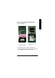
E A-1. Intel C hipset Software Installation Utility Insert the driver CD-title that came with your motherboard into your CD-ROM driver, the driver CD-title will auto start and show the installation guide. If not, please double click the CD-ROM device icon in "My computer", and execute the setup.exe. 1.Click "Intel Chipset Software Installation Utility" item. (1) 2.Click "Next". (2) 3.Click "Yes". 4.Click "Next".
English 5.Click "Finish" to restart computer.
E A-2. Intel Application Accelerator Insert the driver CD-title that came with your motherboard into your CD-ROM driver, the driver CD-title will auto start and show the installation guide. If not, please double click the CD-ROM device icon in "My computer", and execute the setup.exe. 1.Click "Intel Application Accelerator" item. (2) (1) 3.Click "Yes". 2.Click "Next". (4) (3) 4.Click "Next". 5.Click "Next".
English 6.Click "Finish" to restart computer.
E A-3. Intel 845G Chipset VGA Graphics Driver Insert the driver CD-title that came with your motherboard into your CD-ROM driver, the driver CD-title will auto start and show the installation guide. If not, please double click the CD-ROM device icon in "My computer", and execute the setup.exe. 1.Click "Intel 845G Chipset VGA Graphics Driver" item. (1) 2.Click "Next". (2) 3.Click "Yes".
English 4.Click "Finish" to restart computer. (5) A-4. USB Patch Driver Insert the driver CD-title that came with your motherboard into your CD-ROM driver, the driver CD-title will auto start and show the installation guide. If not, please double click the CD-ROM device icon in "My computer", and execute the setup.exe. 1.Click "USB Patch Driver" item. (1) 2.Click "Finish" to restart computer.
E Appendix B: RealTek AC’97 Audio Driver Revision History Insert the driver CD-title that came with your motherboard into your CD-ROM driver, the driver CD-title will auto start and show the installation guide. If not, please double click the CD-ROM device icon in "My computer", and execute the setup.exe. Revision History 2.Click "Next". 1.Click "RealTek AC’97 Audio Driver" item. (2) (1) 3.Click "Finish" to restart computer.
English Appendix C: RealTek 8139/8130/8100 Network Driver * Ø For your reference, you can use the following steps to complete the RealTek 8139/8130/8100 Network Driver Installation. 1.Click "RealTek Network Driver" item. (2) (1) 2.Click "Finish" to restart computer. (4) (3) * For GA-8ILFT Only.
E Appendix D: EasyTune Revision History4 Utilities Installation Insert the driver CD-title that came with your motherboard into your CD-ROM driver, the driver CD-title will auto start and show the installation guide. If not, please double click the CD-ROM device icon in "My computer", and execute the setup.exe. Press "Tools" icon. 2.Click "Easy Tune 4". 1.Click "Gigabyte Utilities". (2) (1) 3.Click "Next". 4.Click "Next". (3) (4) 5.Click "Finish" to restart computer.
English Appendix E: BIOS Flash Procedure BIOS update procedure: Method 1: If your OS is Win9X, we recommend that you used Gigabyte @BIOS TM Program to flash BIOS. 2.Click "@BIOS Writer Utility v.1.08q". Press "Tools" icon. 1.Click "Gigabyte Utilities". (2) (1) Click "P". Click here. (3) Methods and steps: I. Update BIOS through Internet a. Click "Internet Update" icon b. Click "Update New BIOS" icon c.
E II. Update BIOS NOT through Internet: a. Do not click "Internet Update" icon b. Click "Update New BI OS" c. Please select "All Files" in dialog box while opening the old file. d. Please search for BIOS unzip file, downloading from internet or any other methods (such as: 8ILFT.F1). e. Complete update process following the instruction. III. Save BIOS In the very beginning, there is "Save Current B IOS" icon shown in dialog box. It means to save the current BIOS version. IV.
English Method 2: We use GA-7VTX motherboard and Flash841 BIOS flash utility as example. Please flash the BIOS according to the following procedures if you are now under the DOS mode. Flash BIOS Procedure: STEP 1: (1) Please make sure your system has installed the extraction utility such as winzip or pkunzip. Firstly you have to install the extraction utility such as winzip or pkunzip for unzip the files. Both of these utilities are available on many shareware download pages like http://www.shareware.cnet.
E (2) Select the "Quick (erase)" for Format Type, and pick both "Display summary when finished" and "Copy system files", after that press "Start". That will format the floppy and transfer the needed system files to it. Beware: This procedure will erase all the prior data on that floppy, so please proceed accordingly. (3) After the floppy has been formatted completely, please press "Close".
English STEP 3: Download BIOS and BIOS utility program. (1) Please go to Gigabyte website http://www.gigabyte.com.tw/index.html, and click "Support". (2) From Support zone, click the "Motherboards BIOS & Drivers".
E (3) We use GA-7VTX motherboard as example. Please select GA-7VTX by Model or Chipset optional menu to obtain BIOS flash files. (4) Select an appropriate BIOS version (For example: F4), and click to download the file. It will pop up a file download screen, then select the "Open this file from its current location" and press "OK".
English (5) At this time the screen shows the following picture, please click "Extract" button to unzip the files. (6) Please extract the download files into the clean bootable floppy disk A mentioned in STEP 2, and press "E xtract".
E STEP 4: Make sure the system will boot from the floppy disk. (1) Insert the floppy disk (contains bootable program and unzip file) into the floppy drive A. Then, restart the system. The system will boot from the floppy disk. Please press key to enter BIOS setup main menu when system is boot up. (2) Once you enter the BIOS setup utility, the main menu will appear on the screen. Use the arrows to highlight the item "BIOS FEATURES SETUP". AMIBIOS SIMPLE SETUP UTILITY - VERSION 1.
English (3) Press "Enter" to enter "BIOS FEATURES SETUP" menu. Use the arrows to highlight the item "1st Boot Device", and then use the "Page Up" or "Page Down" keys to select "Floppy". AMIBIOS SETUP - BIOS FEATURES SETUP ( C ) 2001 American Megatrends, Inc. All Rights Reserved 1st Boot Device : Floppy 2nd Boot Device : IDE-0 3rd Boot Device : CDROM S.M.A.R.T.
E STEP 5: BIOS flashing. (1) After the system boot from floppy disk, type "A:\> dir/w" and press "Enter" to check the entire files in floppy A. Then type the "BIOS flash utility" and "BIOS file" after A:\>. In this case you have to type "A:\> Flash841 7VTX.F4" and then press "Enter". Starting Windows 98… Microsoft(R) Windows98 © Copyright Microsoft Corp 1981-1999 A:\> dir/w Volume in drive A has no label Volume Serial Number is 16EB-353D Directory of A:\ COMMAND.COM 7VTX .F4 FLASH841.
English (3) It will pop up a screen and asks "Are you sure to flash the BIOS?" Press [Enter] to continue the procedure, or press [ESC] to quit. Beware: Please do not turn off the system while you are upgrading BIOS. It will render your BIOS corrupted and system totally inoperative. Are you sure to flash the BIOS? [Enter] to continue Or [Esc] to cancel? (4) The BIOS flash completed. Please press [ESC] to exit Flash Utility.
E STEP 6: Load BIOS defaults. Normally the system redetects all devices after BIOS has been upgraded. Therefore, we highly recommend reloading the BIOS defaults after BIOS has been upgraded. This important step resets everything after the flash. (1) Take out the floppy diskette from floppy drive, and then restart the system. The boot up screen will indicate your motherboard model and current BIOS version. (2) Don't forget to press key to enter BIOS setup again when system is boot up.
English (3) Use the arrows to highlight the item "SAVE & EXIT SETUP" and press "Enter". System will ask "SAVE t o CMOS and EXIT (Y/N)?" Press "Y" and "E nter" keys to confirm. Now the system will reboot automatically, the new BIOS setting will be taken effect next boot-up. AMIBIOS SIMPLE SETUP UTILITY - VERSION 1.24b (C) 2001 American Megatrends, Inc.
E Appendix E: Acronyms Meaning Advanced Configuration and Power Interface Advanced Power Management Accelerated Graphics Port Audio Modem Riser Advanced Communications Riser Basic Input / Output System Central Processing Unit Complementary Metal Oxide Semiconductor Cont inuity RIMM Communication and Networking Riser Direct Memory Access Desktop Management Interface Dual Inline Memory Module Dual Retention Mechanism Dynamic Random Access Memory Double Data Rate Extended Capabilities Port Extended System Con
English Acronyms LBA LED MHz MI DI MTH MPT NI C OS OE M PA C POST PCI RIMM SCI S ECC SRAM SMP SMI US B VID Meaning Logical Block Addressing Light Emitting Diode Megahertz Musical Interface Digital Interface Memory Translator Hub Memory Protocol Translator Network Interface Card Operating System Original Equipment Manufacturer PCI A.G.P.
E & Technical Support/RMA Sheet Customer/ Country: Contact Person: Company: E-mail Add. : Model name/ Lot Number: BIOS version: O.S./A.S.: Hardware Configuration CP U Memory Brand Video Card Audio Card HDD CD-ROM / DVD-ROM Modem Network AMR / CNR Keyboard Mouse Power supply Other Device Mfs. Phone No.