When you installing AGP card, please make sure the following notice is fully understood and practiced. If your AGP card has "AGP 4X/8X (1.5V) notch"(show below), please make sure your AGP card is AGP 4X/8X. AGP 4X/8X notch Caution: AGP 2X card is not supported by nVIDIA® nForce™ 2 Ultra 400. You might experience system unable to boot up normally. Please insert an AGP Pro 4X/8X card. Example 1: Diamond Vipper V770 golden finger is compatible with 2X/4X mode AGP slot. It can be switched between AGP 2X(3.
The author assumes no responsibility for any errors or omissions that may appear in this document nor does the author make a commitment to update the information contained herein. Third-party brands and names are the property of their respective owners. Please do not remove any labels on motherboard, this may void the warranty of this motherboard. Due to rapid change in technology, some of the specifications might be out of date before publication of this booklet.
Declaration of Conformity We, Manufacturer/Importer (full address) G.B.T.
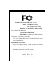
DECLARATION OF CONFORMITY Per FCC Part 2 Section 2.1077(a) Responsible Party Name: G.B.T. INC. (U.S.A.) Address: 17358 Railroad Street City of Industry, CA 91748 Phone/Fax No: (818) 854-9338/ (818) 854-9339 hereby declares that the product Product Name: Motherboard Model Number: GA-7N400 Pro2 /GA-7N400 /GA-7N400-L Conforms to the following specifications: FCC Part 15, Subpart B, Section 15.107(a) and Section 15.
GA-7N400 Pro2 / GA-7N400 / GA-7N400-L AMD Socket A Processor Motherboard USER'S MANUAL AMD Athlon™/ Athlon™ XP / Duron™ Socket A Processor Motherboard Rev.
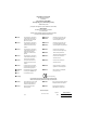
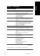
English Table of Content Item Checklist ......................................................................................... 4 Chapter 1 Introduction ............................................................................ 5 Features Summary ...................................................................................... 5 GA-7N400 Pro2 Motherboard Layout ......................................................... 8 GA-7N400 Motherboard Layout ..................................................
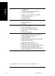
Advanced Chipset Features ...................................................................... 47 Integrated Peripherals .............................................................................. 49 Power Management Setup ....................................................................... 54 PnP/PCI Configurations ............................................................................. 57 PC Health Status ........................................................................................
English Item Checklist The N400 Pro2 / N400 Series motherboard IDE cable x 1 / Floppy cable x 1(23 ) CD for motherboard driver & utility Serial ATA cable x 2 (1) The N400 Pro2 / N400 Series user's manual IEEE1394 cable x 1 (1 ) Quick PC Installation Guide 2 Port USB Cable x 1 GigaRAID manual (1) Audio Combo Kit x 1 (1) SATA RAID manual (1) GC-SATA Card (optional) (SURROUND-Kit + SPDIF Out Kit) (Manual; SATA cable x 1; Power cable x 1) Motherboard Settings Label ATX 12V Cable (*) I/O Shield I
English Chapter 1 Introduction Features Summary Form Factor Motherboard 30.5cm x 24.4cm ATX size form factor, 4 layers PCB N400 Pro2/N400 Series: GA-7N400 Pro2 / GA-7N400 / GA-7N400-L Socket A processor for AMD Athlon™ / Athlon™ XP / Duron™ (K7) 128K L1 & 256K/64K L2 cache on die 400/333/266/200 MHz FSB Supports 1.
English On-Board Peripherals 1 Floppy port supports 2 FDD with 360K, 720K,1.2M, 1.44M and 2.88M bytes 1 Parallel port supports Normal/EPP/ECP mode 2 Serial ports (COM1 & COM2) 6 USB 2.0/1.
Onboard Silicon Image SiI3512 Supports Disk striping (RAID0) or DISK Mirroring (RAID1) Supports UDMA up to 150 MB/sec Up to 2 SATA Device Supports hot plug function Built-in TI TSB43AB23 PS/2 Keyboard interface and PS/2 Mouse interface Licensed AWARD BIOS Supports Dual BIOS (1) Supports Face Wizard Supports Q-Flash PS/2 Keyboard power on by password PS/2 Mouse power on External Modem wake up STR(Suspend-To-RAM) AC Recovery Poly fuse for keyboard over-current protection USB KB/Mouse wake up from S3 Supports
CLK_RATIO KB_MS ATX_12V PWR_FAN English GA-7N400 Pro2 Motherboard Layout COM A ATX RAM_LED USB CPU_FAN Dual Channel DDR FDD LAN USB COM B LPT GA-7N400 Pro2 SOCKET A CD_IN PCI3 AUX_IN BIOS MAIN BIOS SATA0 SATA1 PCI2 SUR_CEN BACKUP PCI4 CI BAT GigaRAID IT8212 SiI3512 TSB43AB23 PCI5 IDE4 IDE3 F_USB SPDIF_IO F_PANEL IR GAME N400 Pro2 / N400 Series Motherboard ¥¼©R¦W-1 8 INFO_LINK F2_1394 IDE1 DDR3 nForce™ 2 MCP PCI1 SYS_FAN nVIDIA® F1_1394 PWR_LED -8- 2005/5/5,
English GA-7N400 Motherboard Layout CLK_RATIO KB_MS ATX_12V Dual Channel DDR FDD USB COM B GA-7N400 LPT SOCKET A ATX RAM_LED COM A USB CPU_FAN AGP IDE1 IDE2 DDR4 SYS_FAN nVIDIA® CLR_CMOS nForce™ 2 MCP PCI1 CD_IN PCI2 SUR_CEN PCI3 AUX_IN MAIN BIOS DDR3 F_AUDIO 2X_DET CODEC IT8712F DDR1 nVIDIA ® nForce™ 2 Ultra 400 CLK_SW DDR2 AUDIO BAT PCI4 CI PCI5 F_USB SPDIF_IO F_PANEL IR GAME INFO_LINK -9- ¥¼©R¦W-1 9 PWR_LED Introduction 2005/5/5, ¤W¤È 11:34
English GA-7N400-L Motherboard Layout CLK_RATIO KB_MS ATX_12V Dual Channel DDR FDD LAN USB COM B GA-7N400-L LPT SOCKET A ATX RAM_LED COM A USB CPU_FAN nVIDIA ® nForce™ 2 AGP CD_IN PCI3 AUX_IN BAT PCI4 CI PCI5 F_USB SPDIF_IO F_PANEL IR GAME N400 Pro2 / N400 Series Motherboard ¥¼©R¦W-1 10 INFO_LINK IDE1 IDE2 DDR4 nForce™ 2 MCP PCI2 SUR_CEN MAIN BIOS SYS_FAN nVIDIA® CLR_CMOS PCI1 CODEC IT8712F DDR1 F_AUDIO 2X_DET RTL8100C DDR3 Ultra 400 CLK_SW DDR2 AUDIO PWR
CPUCLK+/- (100/133/166/200MHz) AMD-K7™ CPU AGP 4X/8X AGPCLK (66MHz) System Bus 400/333/266/200MHz 400/333/266/200MHz nVIDIA® nForce™ 2 Ultra 400 5 PCI DDR RAM RJ45 12 MHz 14.
English N400 Pro2 / N400 Series Motherboard ¥¼©R¦W-1 12 - 12 - 2005/5/5, ¤W¤È 11:35
English Chapter 2 Hardware Installation Process To set up your computer, you must complete the following steps: Step 1- Set system jumper (CLK_SW)& (CLK_RATIO) Step 2- Install the Central Processing Unit (CPU) Step 3- Install memory modules Step 4- Install expansion cards Step 5- Connect ribbon cables, cabinet wires, and power supply Step 1 Step 3 Step 2 Step 5 Step 5 Step 4 Congratulations! You have accomplished the hardware installation! Turn on the power supply or connect the power cable to the pow
English Step 1: Set System Jumper (CLK_SW) & (CLK_RATIO) The clock ratio can be switched by CLK_RATIO and refer to below table.The system bus frequency can be switched at 100MHz and auto by adjusting CLK_SW. O: ON / X :OFF CLK_RATIO Default Setting : Auto (X X X X X X) CLK_RATIO 6 5 4 3 2 1 ON CLK_SW OFF ON CLK_SW ON OFF AUTO 100MHz AUTO : Supports FSB 400/333/266 MHz CPU 100MHz : Fix FSB 200MHz CPU If you want to use a CPU with 200MHz FSB, please set CLK_SW to 100MHz.
Before installing the processor, adhere to the following warning: 1. Please make sure the CPU type is supported by the motherboard. 2. If you do not match the CPU socket Pin 1 and CPU cut edge well, it will cause improper installation. Please change the insert orientation. Step 2-1: CPU Installation CPU Top View CPU Bottom View Pin1 indicator Socket Actuation Lever 1 Pull up the CPU socket lever and up to 90-degree angle. 2.
English Step 2-2: CPU Cooling Fan Installation Before installing the CPU cooling fan, adhere to the following warning: 1. Please use AMD approved cooling fan. 2. We recommend you to apply the thermal tape to provide better heat conduction between your CPU and cooling fan. 3. Make sure the CPU fan power cable is plugged in to the CPU fan connector, this completes the installation. Please refer to CPU cooling fan user's manual for more detail installation procedure. 1.
Before installing the memory modules, adhere to the following warning: 1. When DIMM LED is ON, do not install / remove DIMM from socket. 2. Please note that the DIMM module can only fit in one direction due to the one notch. Wrong orientation will cause improper installation. Please change the insert orientation. The motherboard has 4 dual inline memory module (DIMM) sockets. The BIOS will automatically detects memory type and size. To install the memory module, just push it vertically into the DIMM socket.
English 1. The DIMM socket has a notch, so the DIMM memory module can only fit in one direction. 2. Insert the DIMM memory module vertically into the DIMM socket. Then push it down. 3. Close the plastic clip at both edges of the DIMM sockets to lock the DIMM module. Reverse the installation steps when you wish to remove the DIMM module.
GA-7N400 Pro2 / GA-7N400 / GA-7N400-L support Dual Channel Technology. When Dual Channel Technology is activated, the bandwidth of memory bus will be double the original one, with the fastest speed at 6.4GB/s(DDR400) .
English Step 4: Install expansion cards 1. Read the related expansion card's instruction document before install the expansion card into the computer. 2. Remove your computer's chassis cover, screws and slot bracket from the computer. 3. Press the expansion card firmly into expansion slot in motherboard. 4. Be sure the metal contacts on the card are indeed seated in the slot. 5. Replace the screw to secure the slot bracket of the expansion card. 6. Replace your computer's chassis cover. 7.
Step 5-1: I/O Back Panel Introduction GA-7N400 Pro2 / GA-7N400-L GA-7N400 PS/2 Keyboard and PS/2 Mouse Connector PS/2 Mouse Connector This connector supports standard PS/2 keyboard and PS/2 mouse. (6 pin Female) PS/2 Keyboard Connector (6 pin Female) / Before you connect your device(s) into USB USB/LAN Connector connector(s), please make sure your device(s) such as USB keyboard,mouse, scanner, zip, speaker...etc. Have a standard USB interface.
English Parallel Port, Serial Ports COM1 / COM2 According to your motherboard, please see the following descriptions for the devices. Device like printer can be connected to Parallel port; mouse and modem etc. can be connected to Serial ports. COM1 COM2 Serial Port (9 pin Male) Audio Connectors Line In (Rear Speaker) Line Out (Front Speaker) MIC In (Center and Subwoofer) After install onboard audio driver, you may connect speaker to Line Out jack, microphone to MIC In jack.
1 14 3 5(1 ) 7 2 8 15 16 6(1 ) 4 27 17 10 (1 ) 12 19 20 9 (1 ) 18 26 21 24 23 22(1 ) 25 13 11 1) ATX_12V 2) ATX 15) 2X_DET 16) F_AUDIO 3) 4) 5) 6) CPU_FAN SYS_FAN PWR_FAN(1 ) NB_FAN(1 ) 17) 18) 19) 20) SUR_CEN SPDIF_IO CD_IN AUX_IN 7) 8) 9) 10) FDD IDE1 / IDE2 IDE3 (1 ) / IDE4 (1 ) SATA0 (1 ) / SATA1 (1 ) 21) 22) 23) 24) F_USB F1_1394 (1 ) / F2_1394 (1) IR GAME 11) 12) 13) 14) F_PANEL BAT PWR_LED RAM_LED 25) INFO_LINK 26) CI 27) CLR_CMOS 1 For GA-7N400 Pro2 only.
English 1) ATX_12V (+12V Power Connector) This connector (ATX_12V) supplies the CPU operation voltage (Vcore). If this "ATX_12V connector" is not connected, system cannot boot. Pin No. 1 1 3 2 4 Definition GND 2 GND 3 +12V 4 +12V 2) ATX (ATX Power) AC power cord should only be connected to your power supply unit after ATX power cable and other related devices are firmly connected to the mainboard. Pin No. 11 20 N400 Pro2 / N400 Series Motherboard ¥¼©R¦W-1 24 1 10 Definition 1 3.
Please note, a proper installation of the CPU cooler is essential to prevent the CPU from running under abnormal condition or damaged by overheating. The CPU fan connector supports Max. current up to 600 mA. Pin No. 1 Definition 1 GND 2 3 +12V Sense 4) SYS_FAN (System Fan Connector) This connector allows you to link with the cooling fan on the system case to lower the system temperature. Pin No.
English 5) PWR_FAN (Power Fan Connector)(1 ) This connector allows you to link with the cooling fan on the system case to lower the system temperature. 1 Pin No. Definition 1 GND 2 3 +12V Sense 6) NB_FAN (Chip Fan Connector)(1 ) If you installed wrong direction, the chip fan will not work. Sometimes will damage the chip fan. (Usually black cable is GND) 1 Pin No. 1 2 Definition VCC GND 1 For GA-7N400 Pro2 only. 2 For GA-7N400 only. 3 For GA-7N400-L only.
Please connect the floppy drive ribbon cables to FDD. It supports 360K, 1.2M, 720K, 1.44M and 2.88M bytes floppy disk types. The red stripe of the ribbon cable must be the same side with the Pin1. 34 33 2 1 8) IDE1 / IDE2 (IDE1 / IDE2 Connector) Important Notice: Please connect first hard disk to IDE1 and connect CD-ROM to IDE2. The red stripe of the ribbon cable must be the same side with the Pin1.
English 9) IDE3 / IDE4 (RAID/ATA133, Green Connector)(1) Important Notice: The red stripe of the ribbon cable must be the same side with the Pin1. If you wish to use IDE3 and IDE4, please use it in unity with BIOS (either RAID or ATA133). Then, install the correct driver to have proper operation. For details, please refer to the GigaRAID manual.
Please connect the power LED, PC speaker, reset switch and power switch etc. of your chassis front panel to the F_PANEL connector according to the pin assignment above.
English 12) BATTERY + CAUTION Danger of explosion if battery is incorrectly replaced. Replace only with the same or equivalent type recommended by the manufacturer. Dispose of used batteries according to the manufacturer's instructions. If you want to erase CMOS... 1. Turn OFF the computer and unplug the power cord. 2. Remove the battery, wait for 30 second. 3. Re-install the battery. 4. Plug the power cord and turn ON the computer.
Do not remove memory modules while RAM_LED is on. It might cause short or other unexpected damages due to the stand by voltage. Remove memory modules only when AC power cord is disconnected. + _ 15) 2X_DET When an AGP 2X (3.3V) card is installed the 4X_AGP will light up, indicating a non-supported graphics card is inserted. Informing users that system might not boot up normally due to AGP 2X (3.3V) is not supported by the chipset.
English 16) F_AUDIO (Front Audio Connector) If you want to use Front Audio connector, you must remove 5-6, 9-10 Jumper. In order to utilize the front audio header, your chassis must have front audio connector. Also please make sure the pin assigment on the cable is the same as the pin assigment on the MB header. To find out if the chassis you are buying support front audio connector, please contact your dealer.
The SPDIF output is capable of providing digital audio to external speakers or compressed AC3 data to an external Dolby Digital Decoder. Use this feature only when your stereo system has digital input function. Be careful with the polarity of the SPDIF_IO connector. Check the pin assignment carefully while you connect the SPDIF_IO cable, incorrect connection between the cable and connector will make the device unable to work or even damage it. For optional SPDIF_IO cable, please contact your local dealer.
English 20) AUX_IN (AUX In Connector) Connect other device (such as PCI TV Tunner audio out) to the connector. 1 Pin No. Definition 1 2 AUX-L GND 3 GND 4 AUX-R 21) F_USB (Front USB Connector, Yellow) Be careful with the polarity of the front USB connector. Check the pin assignment carefully while you connect the front USB cable, incorrect connection between the cable and connector will make the device unable to work or even damage it.
( 1) Serial interface standard set by Institute of Electrical and Electronics Engineers, which has features like high speed, highbandwidth and hot plug. Be careful with the polarity of the IEEE1394 connector. Check the pin assignment carefully while you connect the IEEE1394 cable, incorrect connection between the cable and connector will make the device unable to work or even damage it. For optional IEEE1394 cable, please contact your local dealer. 2 16 1 15 F1_1394 F2_1394 Pin No.
English 24) GAME (Game Connector) This connector supports joystick, MIDI keyboard and other relate audio devices. Check the pin assignment while you connect the game cables. Please contact your nearest dealer for optional game cables. Pin No.
This 2-pin connector allows your system to enable or disable the "Case Open" item in BIOS, if the system case begin remove. 1 Pin No. Definition 1 2 Signal GND 27) CLR_CMOS You may clear the CMOS data to its default values by this jumper. Default doesn't include the “Shunter” to prevent from improper use this jumper. To clear CMOS, temporarily short 1-2 pin.
English N400 Pro2 / N400 Series Motherboard ¥¼©R¦W-1 38 - 38 - 2005/5/5, ¤W¤È 11:52
BIOS Setup is an overview of the BIOS Setup Program. The program that allows users to modify the basic system configuration. This type of information is stored in battery-backed CMOS RAM so that it retains the Setup information when the power is turned off. ENTERING SETUP Powering ON the computer and pressing immediately will allow you to enter Setup. If you require more advanced BIOS settings, please go to "Advanced BIOS" setting menu.
English GETTING HELP Main Menu The on-line description of the highlighted setup function is displayed at the bottom of the screen. Status Page Setup Menu / Option Page Setup Menu Press F1 to pop up a small help window that describes the appropriate keys to use and the possible selections for the highlighted item. To exit the Help Window press . The Main Menu (For example: BIOS Ver. : 7N400P2.F6a) Once you enter Award BIOS CMOS Setup Utility, the Main Menu (Figure 1) will appear on the screen.
Advanced Chipset Features English z This setup page includes all the items of Chipset special enhanced features. z Integrated Peripherals This setup page includes all onboard peripherals. z Power Management Setup This setup page includes all the items of Green function features. z PnP/PCI Configurations This setup page includes all the configurations of PCI & PnP ISA resources. z PC Health Status This setup page is the System auto detect Temperature, voltage, fan, speed.
English Standard CMOS Features CMOS Setup Utility-Copyright (C) 1984-2003 Award Software Standard CMOS Features Date (mm:dd:yy) Tue, May 20 2003 Item Help Time (hh:mm:ss) 22:31:24 Menu Level X Change the day, month, ` IDE Primary Master [None] ` IDE Primary Slave [None] year ` IDE Secondary Master [None] ` IDE Secondary Slave [None] Sun. to Sat. Drive A [1.44M, 3.5"] Drive B [None] Jan. to Dec.
The times format in . The time is calculated base on the 24-hour military-time clock. For example, 1 p.m. is 13:00:00. IDE Primary Master, Slave / IDE Secondary Master, Slave The category identifies the types of hard disk from drive C to F that has been installed in the computer. There are two types: auto type, and manual type. Manual type is user-definable; Auto type which will automatically detect HDD type.
English Floppy 3 Mode Support (for Japan Area) Disabled Normal Floppy Drive. (Default value) Drive A Drive A is 3 mode Floppy Drive. Drive B Drive B is 3 mode Floppy Drive. Both Drive A & B are 3 mode Floppy Drives. Halt on The category determines whether the computer will stop if an error is detected during power up. NO Errors The system boot will not stop for any error that may be detected and you will be prompted.
English Advanced BIOS Features CMOS Setup Utility-Copyright (C) 1984-2003 Award Software Advanced BIOS Features XSCSI/RAID Cntlr Boot Order [Press Enter] Item Help First Boot Device [Floppy] Menu Level X Second Boot Device [HDD-0] Select onboard RAID or Third Boot Device [CDROM] PCI SCSI boot rom Boot Up Floppy Seek [Disabled] order Password Check [Setup] Flexible AGP 8X [Auto] Init Display First [PCI] K L J I : Move Enter:Select +/-/PU/PD: Value F10: Save ESC:Exit F5: Previous Values
English USB-ZIP Select your boot device priority by USB-ZIP. USB-CDROM Select your boot device priority by USB-CDROM. USB-HDD Select your boot device priority by USB-HDD. LAN Select your boot device priority by LAN. Disabled Select your boot device priority by Disabled. Boot Up Floppy Seek During POST, BIOS will determine the floppy disk drive installed is 40 or 80 tracks. 360K type is 40 tracks 720K, 1.2M and 1.44M are all 80 tracks.
English Advanced Chipset Features CMOS Setup Utility-Copyright (C) 1984-2003 Award Software Advanced Chipset Features System Performance [Normal] Item Help FSB Frequency [133MHz] Menu Level X Memory Frequency By SPD Resulting Frequency 266MHz [Normal] - Use the AGP Frequency [Normal] most stable settings. [Turbo] -Use over colocked settings for higher performance but with higher risk of instability.
English Memory Frequency By SPD Set memory frequency by SPD. (Default Value) 50%~200% Set the memory frequency manually. Auto Set the best memory frequency for system. Incorrect using it may cause your system to fail. For power End-User use only! Resulting Frequency The value depends on FSB/Memory Frequency. AGP Frequency Normal Set the best AGP frequency for system. (Default Value) 50MHz ~ 100MHz Set the AGP frequency manually. Incorrect using it may cause your system broken.
English Integrated Peripherals CMOS Setup Utility-Copyright (C) 1984-2003 Award Software Integrated Peripherals On-Chip Primary PCI IDE [Enabled] Item Help On-Chip Secondary PCI IDE [Enabled] Menu Level X USB Host Controller [V1.1+V2.
English On-Chip Primary PCI IDE Enabled Enable onboard 1st channel IDE port. (Default value) Disabled Disable onboard 1st channel IDE port. On-Chip Secondary PCI IDE Enabled Enable onboard 2nd channel IDE port. (Default value) Disabled Disable onboard 2nd channel IDE port. USB Host Controller Disabled Disable USB controller. V1.1+V2.0 Set USB controller at USB1.1 and USB2.0. (Default Value) V1.1 Set USB controller at USB1.1. USB Keyboard Support Enabled Enable USB Keyboard Support.
Enabled Auto detect on-chip 1394 function. (Default Value) Disabled Disable this function. English 1) Onboard H/W 1394 (1 1) Onboard H/W Serial ATA (1 Enabled Enable onboard H/W Serial ATA chip function. (Default Value) Disabled Disable this function. 1) Serial ATA Function(1 RAID Select onboard serial ATA chip function as RAID. (Default value) BASE Select onboard serial ATA chip function as base. 1) Onboard H/W RAID (1 Enabled Enable onboard GigaRAID chip function.
English Onboard Serial Port 2 Disabled Disable onboard Serial port 2. 3F8/IRQ4 Enable onboard Serial port 2 and address is 3F8, using IRQ4. 2F8/IRQ3 Enable onboard Serial port 2 and address is 2F8, using IRQ3. (Default value) 3E8/IRQ4 Enable onboard Serial port 2 and address is 3E8, using IRQ4. 2E8/IRQ3 Enable onboard Serial port 2 and address is 2E8, using IRQ3. Auto BIOS will automatically setup the port 2 address.
This feature allows you to select Direct Memory Access(DMA) channel if the ECP mode selected. This function will available when "Parallel Port Mode" set at ECP or ECP+EPP. 3 Set ECP Mode Use DMA to 3. (Default Value) 1 Set ECP Mode Use DMA to 1. Game Port Address Disabled Disable this function. 201 Set Game Port Address to 201. (Default Value) 209 Set Game Port Address to 209. Midi Port Address Disabled Disable this function. 330 Set Midi Port Address to 330.
English Power Management Setup CMOS Setup Utility-Copyright (C) 1984-2003 Award Software Power Management Setup ACPI Suspend Type [S1(POS)] Item Help Soft-Off by PWR-BTTN [Instant-off] Menu Level X PME Event Wake Up [Enabled] [S1] ModemRingOn [Enabled] Set suspend type to S3 Resume by USB [Disabled] Power On Suspend under Resume by Alarm [Disabled] ACPI OS x Date (of Month) Alarm Everyday x Time (hh:mm:ss) Alarm 0:0:0 [S3] Power On by Mouse [Disabled] Set suspend type to Power On
Disabled Disable this function. Enabled Enable PME Event Wake up. (Default Value) English PME Event Wake Up ModemRingOn An incoming call via modem can awake the system from any suspend state . Disabled Disable Modem Ring on function. Enabled Enable Modem Ring on function. (Default Value) S3 Resume by USB You can resume the system from USB device. Disabled Disable this function. (Default Value) Enabled Enable this function.
English KB Power ON Password When "Power On by Keyboard" set at Password, you can set the password here. Enter Input password (from 1 to 5 characters) and press Enter to set the Keyboard Power On password. AC BACK Function Soft-Off When AC-power back to the system, the system will be in "Off" state. (Default Value) Full-On When AC-power back to the system, the system always in "On" state. Memory When AC-power back to the system, the system will return to the Last state before AC-power off.
English PnP/PCI Configurations CMOS Setup Utility-Copyright (C) 1984-2003 Award Software PnP/PCI Configurations PCI 1/PCI 5 IRQ Assignment [Auto] Item Help PCI 2 IRQ Assignment [Auto] Menu Level X PCI 3 IRQ Assignment [Auto] Device(s) using this PCI 4 IRQ Assignment [Auto] INT : Network Cntrlr - Bus 1 Dev 11 Func 0 K L J I : Move Enter:Select +/-/PU/PD: Value F10: Save ESC:Exit F5: Previous Values F6: Fail-Safe Defaults F1: General Help F7: Optimized Defaults Figure 7: PnP/PCI Configuration
English PC Health Status CMOS Setup Utility-Copyright (C) 1984-2003 Award Software PC Health Status Reset Case Open Status [Disabled] Item Help Case Opened Yes Menu Level X Vcore OK [Disabled] DDR25V OK Don't reset case +3.
English Current Voltage (V) Vcore / DDR25V / +3.3V / +5V / +12V Detect system's voltage status automatically. Current System Temperature Detect System temperature automatically. Current CPU Temperature Detect CPU temperature automatically. Current CPU/POWER1/SYSTEM FAN Speed (RPM) Detect CPU/POWER/SYSTEM Fan speed status automatically. CPU Warning Temperature 60 o C / 140 o F 70 o C / 158 o F 80 o C / 176 o F 90 o C / 194 o F Disabled Monitor CPU Temp. at 60o C / 140o F. Monitor CPU Temp.
English Frequency/Voltage Control CMOS Setup Utility-Copyright (C) 1984-2003 Award Software Frequency/Voltage Control VCORE OverVoltage Control [Normal] Item Help DIMM OverVoltage Control [Normal] Menu Level X AGP OverVoltage Control [Normal] K L J I: Move Enter:Select +/-/PU/PD: Value F10: Save ESC:Exit F5: Previous Values F6: Fail-Safe Defaults F1: General Help F7: Optimized Defaults Figure 9: Frequency/Voltage Control VCORE OverVoltage Control Increase VCORE voltage may get stable for Over_
English Load Fail-Safe Defaults CMOS Setup Utility-Copyright (C) 1984-2003 Award Software ` Standard CMOS Features ` Frequency/Voltage Control ` Advanced BIOS Features Load Fail-Safe Defaults ` Advanced Chipset Features Load Optimized Defaults Y ` Integrated PeripheralsLoad Fail-Safe Defaults (Y/N) Set?Supervisor Password ` Power Management Setup Set User Password ` PnP/PCI Configurations Save & Exit Setup ` PC Health Status Exit Without Saving ESC: Quit KLJI: Select Item F8: Dual BIOS / Q-Fl
English Load Optimized Defaults CMOS Setup Utility-Copyright (C) 1984-2003 Award Software ` Standard CMOS Features ` Frequency/Voltage Control ` Advanced BIOS Features Load Fail-Safe Defaults ` Advanced Chipset Features Load Optimized Defaults ` Y Integrated PeripheralsLoad Optimized Defaults (Y/N) Set ? Supervisor Password ` Power Management Setup Set User Password ` PnP/PCI Configurations Save & Exit Setup ` PC Health Status Exit Without Saving ESC: Quit KLJI: Select Item F8: Dual BIOS /
English Set Supervisor/User Password CMOS Setup Utility-Copyright (C) 1984-2003 Award Software ` Standard CMOS Features ` Frequency/Voltage Control ` Advanced BIOS Features Load Fail-Safe Defaults ` Advanced Chipset Features Load Optimized Defaults Enter Password: ` Integrated Peripherals Set Supervisor Password ` Power Management Setup Set User Password ` PnP/PCI Configurations Save & Exit Setup ` PC Health Status Exit Without Saving ESC: Quit KLJI: Select Item F8: Dual BIOS / Q-Flash F10
English Save & Exit Setup CMOS Setup Utility-Copyright (C) 1984-2003 Award Software ` Standard CMOS Features ` Frequency/Voltage Control ` Advanced BIOS Features Load Fail-Safe Defaults ` Advanced Chipset Features Load Optimized Defaults ` Integrated Peripherals Set Supervisor Password ` Power Management Setup Set User Password ` PnP/PCI Configurations Save & Exit Setup ` PC Health Status Exit Without Saving Save to CMOS and EXIT (Y/N) ? Y ESC: Quit KLJI: Select Item F8: Dual BIOS / Q-Flas
English Exit Without Saving CMOS Setup Utility-Copyright (C) 1984-2003 Award Software ` Standard CMOS Features ` Frequency/Voltage Control ` Advanced BIOS Features Load Fail-Safe Defaults ` Advanced Chipset Features Load Optimized Defaults ` Integrated Peripherals Set Supervisor Password ` Power Management Setup Set User Password ` PnP/PCI Configurations Save & Exit Setup ` PC Health Status Exit Without Saving Quit Without Saving (Y/N)? N ESC: Quit KLJI: Select Item F8: Dual BIOS / Q-Flash
English N400 Pro2 / N400 Series Motherboard - 66 -
English Chapter 4 Technical Reference @BIOS™ Introduction Gigabyte announces @ B I O S Windows BIOS Live Update Utility Have you ever updated BIOS by yourself? Or like many other people, you just know what BIOS is, but always hesitate to update it? Because you think updating newest BIOS is unnecessary and actually you don't know how to update it. Maybe not like others, you are very experienced in BIOS updating and spend quite a lot of time to do it. But of course you don't like to do it too much.
English Flash BIOS Method Introduction Method 1 : Dual BIOS (1) / Q-Flash A. What is Dual BIOS Technology? Dual BIOS means that there are two system BIOS (ROM) on the motherboard, one is the Main BIOS and the other is Backup BIOS. Under the normal circumstances, the system works on the Main BIOS. If the Main BIOS is corrupted or damaged, the Backup BIOS can take over while the system is powered on. This means that your PC will still be able to run stably as if nothing has happened in your BIOS. B.
English 2.) Award Dual BIOS Flash ROM Programming Utility Dual BIOS Utility V1.30 Boot From....................................................... Main ROM Type/Size...................................... Backup ROM Type/Size..................................
English • Auto Recovery : Enable(Default), Disable When one of the Main BIOS or Backup BIOS occurs checksum failure, the working BIOS will automatically recover the BIOS of checksum failure. (In the Power Management Setup of the BIOS Setting, if ACPI Suspend Type is set to Suspend to RAM, the Auto Recovery will be set to Enable automatically.) (If you want to enter the BIOS setting, please press"Del" key when the boot screen appears.
Q-Flash utility is a pre-O.S. BIOS flash utility enables users to update its BIOS within BIOS mode, no more fooling around any OS. D. How to use Q-Flash? Update Main BIOS from Floppy / Update Backup BIOS from Floppy In the A: drive, insert the "BIOS" diskette, then Press Enter to Run. 1 File(s) found XXXX.XX 256K Total Size: 1.39M F5: Refresh Free Size: 1.14M DEL: Delete ESC: Return Main Where XXXX.XX is name of the BIOS file. Press Enter to Run.
English Save Main BIOS to Floppy / Save Backup BIOS to Floppy In the A:drive, insert the floppy disk, then Press Enter to Run. TYPE FILE NAME File name: XXXX.XX Total Size: 1.39M F5: Refresh DEL: Delete Free Size: 1.39M TAB: Switch To name the file. Congratulate you have accomplished the saving.
GIGABYTE Technology is pleased to introduce DualBIOS technology, a hot spare for your system BIOS. This newest "Value-added" feature, in a long series of innovations from GIGABYTE, is available on this motherboard. Future GIGABYTE motherboards will also incorporate this innovation. What's DualBIOS™? On GIGABYTE motherboards with DualBIOS there are physically two BIOS chips. For simplicity we'll call one your "Main BIOS" and the other we'll call your "Backup BIOS" (your "hot spare").
English II. Q: Why does anyone need a motherboard with DualBIOS™ technology? Answer: In today's systems there are more and more BIOS failures. The most common reasons are virus attacks, BIOS upgrade failures, and/or deterioration of the BIOS (ROM) chip itself. 1. New computer viruses are being found that attack and destroy the system BIOS. They may corrupt your BIOS code, causing your PC to be unstable or even not boot normally. 2.
This new technology will eliminate valuable system down time and costly repair bills cause by BIOS failures. 1. Every user should have DualBIOS™ technology due to the advancement of computer viruses. Everyday, there are new BIOS-type viruses discovered that will destroy your system BIOS. Most commercial products on the market do not have solutions to guard against this type of virus intrusion. The DualBIOS™ technology will provide a state-of-the-art solution to protect your PC: Case I.
English Method 2 : @BIOS™ Utility If you don't have DOS boot disk, we recommend that you used Gigabyte @BIOS™ program to flash BIOS. Press here. 2. Click Start/ Programs/ GIGABYTE/ @BIOS. 1. Click "@BIOS" item. (1) 3.Click " ". (2) Click here 4. Please select @BIOS sever site, then Click "OK". (3) (4) Methods and steps: I. Update BIOS through Internet a. b. c. d. Click "Internet Update" icon Click "Update New BIOS" icon Select @BIOS™ sever Select the exact model name on your motherboard e.
a. b. c. d. Do not click "Internet Update" icon Click "Update New BIOS" Please select "All Files" in dialog box while opening the old file. Please search for BIOS unzip file, downloading from internet or any other methods. (such as: 7N400P2.F1). e. Complete update process following the instruction. III. Save BIOS In the very beginning, there is "Save Current BIOS" icon shown in dialog box. It means to save the current BIOS version. IV.
English 2- / 4- / 6-Channel Audio Function Introuction The installation of Windows 98SE/2K/ME/XP is very simple. Please follow next step to install the function! Stereo Speakers Connection and Settings: We recommend that you use the speaker with amplifier to acqiire the best sound effect if the stereo output is applied. STEP 1: Connect the stereo speakers or earphone to "Line Out". Line Out STEP 2 : After installation of the audio driver, you'll find an icon on the taskbar's status area.
English 4 Channel Analog Audio Output Mode STEP 1 : Connect the front channels to "Line Out", the rear channels to "Line In". Line Out Line In STEP 2 : After installation of the audio driver, you'll find an icon on the taskbar's status area. Click the audio icon "Sound Effect" from the windows tray at the bottom of the screen. STEP 3 : Select "Speaker Configuration", and choose the "4 channel for 4 speakers output". Disable "Only SURROUND-KIT", and press "OK".
English Basic 6 Channel Analog Audio Output Mode Use the back audio panel to connect the audio output without any additional module. STEP 1 : Connect the front channels to "Line Out", the rear Line In channels to "Line In", and the Center/Subwoofer channels to "MIC In". MIC In STEP 2 : After installation of the audio driver, you'll find an icon on the taskbar's status area. Click the audio icon "Sound Effect" from the windows tray at the bottom of the screen.
(Audio Combo Kit provides SPDIF output port : optical & coaxis and SURROUND-KIT : Rear R/L & Center/subwoofer) SURROUND-KIT access analog output to rear channels and Center/Subwoofer channels. It is the best solution if you need 6 channel output, Line In and MIC at the same time. "SURROUND-KIT" is included in the GIGABYTE unique "Audio Combo Kit" as picture. STEP 1 : Insert the "Audio Combo Kit" in the back of the case, and fix it with the screw. STEP 2 : Connect the "SURROUND-KIT" to SUR_CEN on the M/B.
English STEP 3 : Connect the front channels to back audio panel's "Line Out", the rear channels to SURROUND-KIT's REAR R/L, and the Center/Subwoofer channels to SURROUND-KIT's SUB CENTER. STEP 4 : Click the audio icon "Sound Effect" from the windows tray at the bottom of the screen. STEP 5 : Select "Speaker Configuration", and choose the "6 channels for 5.1 speakers out put". Enable "Only SURROUND-KIT" and press "OK".
English SPDIF Output Device (Optional Device) A "S/PDIF output" device is available on the motherboard. Cable with rear bracket is provided and could link to the "S/PDIF output" connector (As picture.) For the further linkage to decoder, rear bracket provides coaxial cable and Fiber connecting port. 1. Connect the SPDIF output device to the rear bracket of PC, and fix it with screw. 2. Connect SPDIF wire to the motherboard. 3. Connect co-axial or optical output to the AC3 decoder.
English Xpress Recovery Introduction What is Xpress Recovery? Xpress Recovery utility is an utility for backing up and restoring O.S. partition . If the hard drive can not work properly, you can restore it to the original state. 1. It supports FAT16 ¡BFAT32 ¡BNTFS format . 2. It must be connected to IDE1 Master . 3. It's only allows you to install one O.S . 4. It must be used with IDE hard disk supporting HPA . 5. The first partition must be set as the boot partition.
Xpress Recovery V1.0 (C) Copy Right 2003. GIGABYTE Technilogy CO. , Ltd. 1. Execute Backup Utility 2. Execute Restore Utility 3. Remove Backup Image 4. Exit and Restart BMP Mode: Xpress Recovery V1.0 (C) Copy Right 2003. GIGABYTE Technilogy CO. , Ltd. 1. Execute Backup Utility 2. Execute Restore Utility 3. Remove Backup Image 4. Exit and Restart If you ever entered Xpress Recovery by booting from CD-ROM, you'll still be directed to BMP mode by pressing F9 in the bootup screen.
English 1.Execute Backup Utility: Press B to Backup your System or Esc to Exit The Backup utility will scan the system automatically and back up it. The backed up data will be saved as an hidden image . 2.Execute Restore Utility: This program will recover your system to factory default. Press R to recover your system. Press Esc to exit Restore the backup image to the original state. 3.Remove Backup Image: Are you sure to remove backup image? (Y/N) Remove the backup image. 4.
English - 87 - Technical Reference
English N400 Pro2 / N400 Series Motherboard - 88 -
English Revision ChapterHistory 5 Appendix Install Drivers Pictures below are shown in Windows XP Insert the driver CD-title that came with your motherboard into your CD-ROM drive, the driver CD-title will auto start and show the installation guide. If not, please double click the CD-ROM device icon in "My computer", and execute the setup.exe. INSTALL CHIPSET DRIVER This page shows the drivers that need to be installed for the system.
English Driver installation finished ! You have to reboot system ! Item Description Nvidia System Driver nVIDIA Chipset Driver USB Patch for WinXP This patch driver can help you to resolve the USB device wake up S3 hang up issue in XP.
This page reveals the value-added software developed by Gigabyte and its worldwide partners.
English SOFTWARE INFORMATION This page list the contects of softwares and drivers in this CD title. HARDWARE INFORMATION This page lists all device you have for this motherboard. CONTACT US Please see the last page for details.
What is Face-Wizard™ ? Face-WizardTM is a windows based utility with user-friendly interface that allows users to change the boot-up logo with picture from Gigabyte Logo Gallery on web site or other compatible picture you have. How does it work? Face-Wizard™ allows user to select BIOS on board or file in hard drive, floppy disk, zip, MO or other storage devices and combine the compatible picture you prefer into BIOS. And not only this, Face-Wizard™ also helps user to update BIOS in windows mode.
English FAQ Below is a collection of general asked questions. To check generally asked questions based on a specific motherboard model, please go to the FAQ section at GIGABYTE’s website. Question 1: I cannot see some options that were included in previous BIOS after updating BIOS. Why? Answer: Some advanced options are hidden in new BIOS version. Please press Ctrl and F1 keys after entering BIOS menu and you will be able to see these options.
Question 9: Why cannot I use the IDE 2? Answer: Please refer to the user manual and check whether you have connected any cable that is not provided with the motherboard package to the USB Over Current pin in the Front USB Panel. If the cable is your own cable, please remove it from this pin and do not connect any of your own cables to it. Question 10: Sometimes I hear different continuous beeps from computer after system boots up.
English Troubleshooting If you encounter any trouble during boot up, please follow the troubleshooting procedures. START Turn off the power and unplug the AC power cable, then remove all of the add-on cards and cables from motherboard. Please make sure motherboard & chassis are not short ? Yes Please isolate the short pin. No Failure has been excluded. Please make sure all jumper settings (such as CPU system bus speed, frequency ratio, voltage and etc) are set properly.
Is memory LED on and CPU fan running? No The problem could be caused by power supply, CPU, memory or CPU/memory socket itself. Yes Failure has been excluded. No Check if there is display. Yes Perhaps your VGA card / VGA slot or monitor is defective. Failure has been excluded. Turn off the system. Reboot after keyboard and mouse have been plugged in. Check if keyboard is working properly. No It is possible that your keyboard or keyboard connector is defective. Yes Press to enter BIOS setup.
English Technical Support/RMA Sheet Customer/Country: Company: Contact Person: E-mail Add. : Model name/Lot Number: BIOS version: O.S./A.S.: Hardware Model name Mfs. Phone No.
Acronyms Meaning ACPI APM Advanced Configuration and Power Interface Advanced Power Management AGP AMR Accelerated Graphics Port Audio Modem Riser ACR BIOS Advanced Communications Riser Basic Input / Output System CPU CMOS Central Processing Unit Complementary Metal Oxide Semiconductor CRIMM CNR Continuity RIMM Communication and Networking Riser DMA DMI Direct Memory Access Desktop Management Interface DIMM DRM Dual Inline Memory Module Dual Retention Mechanism DRAM DDR Dynamic Random Acces
English Acronyms IOAPIC Meaning Input Output Advanced Programmable Input Controller ISA LAN Industry Standard Architecture Local Area Network I/O LBA Input / Output Logical Block Addressing LED MHz Light Emitting Diode Megahertz MIDI MTH Musical Instrument Digital Interface Memory Translator Hub MPT NIC Memory Protocol Translator Network Interface Card OS OEM Operating System Original Equipment Manufacturer PAC POST PCI A.G.P.
English - 101 - Appendix
English N400 Pro2 / N400 Series Motherboard - 102 -
English - 103 - Appendix
English N400 Pro2 / N400 Series Motherboard - 104 -
English - 105 - Appendix
English N400 Pro2 / N400 Series Motherboard - 106 -
English Contact Us Taiwan (Headquarters) GIGA-BYTE TECHNOLOGY CO., LTD. Japan NIPPON GIGA-BYTE CORPORATION Address: No.6, Bau Chiang Road, Hsin-Tien, Taipei Hsien, Taiwan. WEB address : http://www.gigabyte.co.jp Singapore TEL: +886 (2) 8912-4888 FAX: +886 (2) 8912-4003 GIGA-BYTE SINGAPORE PTE. LTD. Tech. Support : Tech. Support : http://tw.giga-byte.com/TechSupport/ServiceCenter.htm http://tw.giga-byte.com/TechSupport/ServiceCenter.htm Non-Tech. Support(Sales/Marketing) : Non-Tech.
English China Australia NINGBO G.B.T. TECH. TRADING CO., LTD. Tech. Support : GIGABYTE TECHNOLOGY PTY. LTD. Tech. Support : http://cn.giga-byte.com/TechSupport/ServiceCenter.htm Non-Tech. Support(Sales/Marketing) : http://www.giga-byte.com.au/TechSupport/ServiceCenter.htm Non-Tech. Support(Sales/Marketing) : http://ggts.gigabyte.com.tw/nontech.asp WEB address : http://www.gigabyte.com.cn http://ggts.gigabyte.com.tw/nontech.asp WEB address : http://www.giga-byte.com.