GA-7N400S / GA-7N400S-L AMD Sempron / Athlon XP / Athlon / Duron Socket A Processor Motherboard TM User's Manual Rev.
Motherboard GA-7N400S Oct. 18, 2004 Motherboard GA-7N400S Oct.
Copyright © 2004 GIGA-BYTE TECHNOLOGY CO., LTD. All rights reserved. The trademarks mentioned in the manual are legally registered to their respective companies. Notice The written content provided with this product is the property of Gigabyte. No part of this manual may be reproduced, copied, translated, or transmitted in any form or by any means without Gigabyte's prior written permission. Specifications and features are subject to change without prior notice.
Table of Contents GA-7N400S/GA-7N400S-L Motherboard Layout .......................................................... 6 Block Diagram ............................................................................................................... 7 Chapter 1 Hardware Installation ................................................................................... 9 1-1 1-2 Considerations Prior to Installation ................................................................. 9 Feature Summary ................
Chapter 3 Drivers Installation ..................................................................................... 47 3-1 Install Chipset Drivers ................................................................................... 47 3-2 3-3 Software Application ...................................................................................... 48 Software Information ..................................................................................... 48 3-4 3-5 Hardware Information ..............
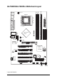
DDR3 ATX_12V KB_MS DDR2 DDR1 GA-7N400S/GA-7N400S-L Motherboard Layout SOCKET A R_USB GA-7N400S CLK_SW AUX_IN SUR_CEN RTL8100C* nVIDIA nForce 2 Ultra 400 CD_IN F_AUDIO MIC_IN USB LINE_OUT LINE_IN LAN* COMB LPT COMA ATX IDE2 IDE1 CPU_FAN AGP PCI1 nVIDIA nForce 2 MCP RAID PCI2 SPDIF_IO SATA0 PCI3 CODEC IT8712 PCI4 -L* SATA1 BIOS BAT CLR_CMOS FDD PCI5 PWR_LED IR F_USB1 F_USB2 F_PANEL * Only for GA-7N400S-L.
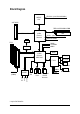
Block Diagram AMD-K7 CPU CPUCLK+/-(100/133/166/200MHz) AGP 4X/8X DDR 400/333/266MHz DIMM AGPCLK 66MHz nVIDIA nForce 2 Ultra 400 DDR HCLK+/- (100/133/166/200MHz) NBGCLK 66 MHz RJ45* 5 PCI 33MHz 14.318MHz 48MHz RTL8100C* PCI Bus 33MHz nVIDIA nForce 2 MCP RAID BIOS Floppy AC97 Link IT8712 LPT Port 2 COM Ports 24MHz Line Out Mic In Line In PCICLK (33MHz) CODEC 2 Serial ATA 8 USB ATA33/66/100/ Ports 133 IDE Channels * Only for GA-7N400S-L.
-8-
1-1 English Chapter 1 Hardware Installation Considerations Prior to Installation Preparing Your Computer The motherboard contains numerous delicate electronic circuits and components which can become damaged as a result of electrostatic discharge (ESD). Thus, prior to installation, please follow the instructions below: 1. Please turn off the computer and unplug its power cord. 2. When handling the motherboard, avoid touching any metal leads or connectors. 3.
English 1-2 Feature Summary Motherboard CPU Chipset Memory Slots IDE Connections FDD Connections Onboard SATA Peripherals Onboard LAN* Onboard Audio I/O Control Hardware Monitor BIOS Additional Features Overclocking Form Factor GA-7N400S or GA-7N400S-L Socket A for AMD Sempron TM / AthlonTM XP / AthlonTM / Duron TM processor Supports 200/266/333/400MHz FSB Supports 1.
Set System Clock (CLK_SW) The system bus frequency can be switched at 100/133/166/200MHz by adjusting CLK_SW. (The internal frequency depend on CPU.) ON ON: Auto (133/166/200MHz, supports the 266/333/ 400MHz FSB CPU, Default) OFF ON OFF OFF: FORCE 100MHz (supports the 200MHz FSB CPU) When you use a CPU with 200MHz FSB, please do set the CLK_SW to OFF (100MHz).
English 1-4-1 Installation of the CPU Pin 1(indented corner) Position lever at a 90-degree angle indented corner Fig. 1 Gently lift the CPU socket lever and up to a 90-degree angle. Fig. 2 A gold-colored triangle is marked one edge of the CPU. Please align this edge with the socket edge closest to the CPU lever. Gently place the CPU into position making sure that the CPU pins fit perfectly into their holes.
Installation of Memory Before installing the memory modules, please comply with the following conditions: 1. Please make sure that the memory used is supported by the motherboard. It is recommended that memory of similar capacity, specifications and brand be used. 2. Before installing or removing memory modules, please make sure that the computer power is switched off to prevent hardware damage. 3. Memory modules have a foolproof insertion design. A memory module can be installed in only one direction.
English Dual Channel DDR GA-7N400S / GA-7N400S-L supports the Dual Channel Technology. After operating the Dual Channel Technology, the bandwidth of Memory Bus will add double up to 6.4GB/s(DDR400) or 5.3GB/s(DDR333). GA-7N400S / GA-7N400S-L includes 3 DIMM sockets as following: Channel A : DDR 1, DDR 2 Channel B : DDR 3 If you want to operate the Dual Channel Technology, please note the following explanations due to the limitation of Intel chipset specifications. 1.
Installation of Expansion Cards You can install your expansion card by following the steps outlined below: 1. Read the related expansion card's instruction document before install the expansion card into the computer. 2. Remove your computer's chassis cover, screws and slot bracket from the computer. 3. Press the expansion card firmly into expansion slot in motherboard. 4. Be sure the metal contacts on the card are indeed seated in the slot. 5.
English 1-7 I/O Back Panel Introduction * PS/2 Keyboard and PS/2 Mouse Connector To install a PS/2 port keyboard and mouse, plug the mouse to the upper port (green) and the keyboard to the lower port (purple). USB port Before you connect your device(s) into USB connector(s), please make sure your device(s) such as USB keyboard, mouse, scanner, zip, speaker...etc. have a standard USB interface. Also make sure your OS supports USB controller.
Connectors Introduction 1 English 1-8 2 6 13 11 12 3 14 7 15 9 18 5 4 16 8 17 1) 2) 3) 4) 5) 6) 7) 8) 9) ATX_12V ATX (Power Connector) CPU_FAN SYS_FAN FDD IDE1 / IDE2 SATA0 / SATA1 PWR_LED BAT 10) 11) 12) 13) 14) 15) 16) 17) 18) - 17 - 10 F_PANEL F_AUDIO SUR_CEN CD_IN AUX_IN SPDIF_IO F_USB1 / F_USB2 IR CLR_CMOS Hardware Installation
English 1/2) ATX_12V / ATX (Power Connector) With the use of the power connector, the power supply can supply enough stable power to all the components on the motherboard. Before connecting the power connector, please make sure that all components and devices are properly installed. Align the power connector with its proper location on the motherboard and connect tightly. The ATX_12V power connector mainly supplies power to the CPU.
The cooler fan power connector supplies a +12V power voltage via a 3-pin power connector and possesses a foolproof connection design. Most coolers are designed with color-coded power connector wires. A red power connector wire indicates a positive connection and requires a +12V power voltage. The black connector wire is the ground wire (GND). Please remember to connect the power to the cooler to prevent system overheating and failure.
English 6) IDE1 / IDE2 (IDE Connector) An IDE device connects to the computer via an IDE connector. One IDE connector can connect to one IDE cable, and the single IDE cable can then connect to two IDE devices (hard drive or optical drive). If you wish to connect two IDE devices, please set the jumper on one IDE device as Master and the other as Slave (for information on settings, please refer to the instructions located on the IDE device).
PWR_LED is connect with the system power indicator to indicate whether the system is on/off. It will blink when the system enters suspend mode. Pin No. 1 Definition 1 MPD+ 2 3 MPDMPD- 9) BAT(Battery) Danger of explosion if battery is incorrectly replaced. Replace only with the same or equivalent type recommended by the manufacturer. Dispose of used batteries according to the manufacturer's instructions. If you want to erase CMOS... 1. Turn OFF the computer and unplug the power cord. 2.
Please connect the power LED, PC peaker, reset switch and power switch etc. of your chassis front panel to the F_PANEL connector according to the pin assignment below.
If you want to use Front Audio connector, you must remove 5-6, 9-10 Jumper. In order to utilize the front audio header, your chassis must have front audio connector. Also please make sure the pin assigment on the cable is the same as the pin assigment on the MB header. To find out if the chassis you are buying support front audio connector, please contact your dealer. Please note, you can have the alternative of using front audio connector or of using rear audio connector to play sound. Pin No.
English 13/14) CD_IN (CD In Connector, black) / AUX_IN (AUX In Connector, white) Connect CD-ROM or DVD-ROM audio out to the CD_IN connector. Connect other device(such as PCI TV Tunner audio out) to the AUX_IN connector. Pin No. 1 1 (CD_IN, black) 1 2 3 GND GND 4 CD-R Pin No.
Be careful with the polarity of the front USB connector. Check the pin assignment carefully while you connect the front USB cable, incorrect connection between the cable and connector will make the device unable to work or even damage it. For optional front USB cable, please contact your local dealer. Pin No. 2 1 10 9 Definition 1 2 Power Power 3 4 USB DXUSB Dy- 5 6 USB DX+ USB Dy+ 7 8 GND GND 9 10 No Pin NC 17) IR Be careful with the polarity of the IR connector while you connect the IR.
English 18) CLR_CMOS (Clear CMOS) You may clear the CMOS data to its default values by this jumper. To clear CMOS, temporarily short 1-2 pin. Default doesn't include the "Shunter" to prevent from improper use this jumper.
BIOS (Basic Input and Output System) includes a CMOS SETUP utility which allows user to configure required settings or to activate certain system features. The CMOS SETUP saves the configuration in the CMOS SRAM of the motherboard. When the power is turned off, the battery on the motherboard supplies the necessary power to the CMOS SRAM. When the power is turned on, pushing the button during the BIOS POST (Power-On Self Test) will take you to the CMOS SETUP screen.
English The Main Menu (For example: BIOS Ver. : E17) Once you enter Award BIOS CMOS Setup Utility, the Main Menu (as figure below) will appear on the screen. Use arrow keys to select among the items and press to accept or enter the sub-menu.
Optimized Defaults indicates the value of the system parameters which the system would be in best performance configuration. Set Supervisor Password Change, set, or disable password. It allows you to limit access to the system and Setup, or just to Setup. Set User Password Change, set, or disable password. It allows you to limit access to the system. Save & Exit Setup Save CMOS value settings to CMOS and exit setup. Exit Without Saving Abandon all CMOS value changes and exit setup.
English 2-1 Standard CMOS Features CMOS Setup Utility-Copyright (C) 1984-2004 Award Software Standard CMOS Features ` ` ` ` ` ` Date (mm:dd:yy) Time (hh:mm:ss) Tue, Sep 21 2004 22:31:24 Item Help Menu Level` IDE Channel 0 Master IDE Channel 0 Slave IDE Channel 1 Master IDE Channel 1 Slave IDE Channel 2 Master IDE Channel 3 Master [None] [None] [None] [None] [None] [None] Change the day, month, year Drive A Drive B Floppy 3 Mode Suport [1.44M, 3.
The category identifies the types of floppy disk drive A or drive B that has been installed in the computer. None No floppy drive installed 360K, 5.25" 5.25 inch PC-type standard drive; 360K byte capacity. 1.2M, 5.25" 5.25 inch AT-type high-density drive; 1.2M byte capacity (3.5 inch when 3 Mode is Enabled). 720K, 3.5" 3.5 inch double-sided drive; 720K byte capacity 1.44M, 3.5" 3.5 inch double-sided drive; 1.44M byte capacity. 2.88M, 3.5" 3.5 inch double-sided drive; 2.88M byte capacity.
English 2-2 Advanced BIOS Features CMOS Setup Utility-Copyright (C) 1984-2004 Award Software Advanced BIOS Features ` Hard Disk Boot Priority First Boot Device Second Boot Device Third Boot Device Boot Up Floppy Seek Password Check Init Display First [Press Enter] [Floppy] [Hard Disk] [CDROM] [Disabled] [Setup] [PCI Slot] KLJI: Move Enter: Select F5: Previous Values +/-/PU/PD: Value F6: Fail-Save Defaults F10: Save Item Help Menu Level` Select Hard Disk Boot Device Priority ESC: Exit F1: General He
Setup System The system will boot but will not access to Setup page if the correct password is not entered at the prompt. (Default value) The system will not boot and will not access to Setup page if the correct password is not entered at the prompt. Init Display First This feature allows you to select the first initiation of the monitor display from which card when you install an AGP card and a PCI VGA card on board. PCI Slot Set initial display first to PCI slot.
English 2-3 Advanced Chipset Features CMOS Setup Utility-Copyright (C) 1984-2004 Award Software Advanced Chipset Features System Performance FSB Frequency x Memory Frequency Resulting Frequency AGP Frequency [Normal] [100MHz] By SPD 266MHz [Normal] Item Help Menu Level` [Normal] Use the most stable settings [Turbo] Use over clocked settings for higher performance but with higher risk of instability [Manual] Allows full customization of performance options Advanced users only KLJI: Move Enter: Select F
Integrated Peripherals English 2-4 CMOS Setup Utility-Copyright (C) 1984-2004 Award Software Integrated Peripherals ` IDE Function Setup ` RAID Config OnChip USB USB Keyboard Support USB Mouse Support AC97 Audio Onboard H/W LAN* Onboard Serial Port 1 Onboard Serial Port 2 UART Mode Select x UR2 Duplex Mode Onboard Parallel Port Parallel Port Mode ECP Mode Use DMA Game Port Address Midi Port Address x Midi Port IRQ [Press Enter] [Press Enter] [V1.1+V2.
English SATA DMA Transfer Enabled Disabled Enable Serial ATA transfer function. (Default value) Disable this function. SATA Spread Spectrum Enabled Disabled Enable Serial ATA spread spectrum function. Disable this function.
Disabled V1.1+V2.0 V1.1 English OnChip USB Disable USB controller. Set USB controller at USB1.1 and USB2.0. (Default value) Set USB controller at USB1.1. USB Keyboard Support Enabled Disabled Enable USB keyboard support. Disable USB keyboard support. (Default value) USB Mouse Support Enabled Disabled Enable USB mouse support. Disable USB mouse support. (Default value) AC97 Audio Auto Disabled Auto detect AC97 audio function. (Default value) Disable AC97 audio function.
English Onboard Parallel port Disabled 378/IRQ7 278/IRQ5 3BC/IRQ7 Disable onboard LPT port. Enable onboard LPT port and address is 378/IRQ7. (Default value) Enable onboard LPT port and address is 278/IRQ5. Enable onboard LPT port and address is 3BC/IRQ7. Parallel Port Mode SPP EPP ECP ECP+EPP Using Parallel port as Standard Parallel Port. Using Parallel port as Enhanced Parallel Port. Using Parallel port as Extended Capabilities Port. (Default value) Using Parallel port as ECP & EPP mode.
Power Management Setup English 2-5 CMOS Setup Utility-Copyright (C) 1984-2004 Award Software Power Management Setup ACPI Suspend Type Soft-Off by PWR-BTTN PME Event Wake Up ModemRingOn S3 Resume by USB Resume by Alarm x Date (of Month) Alarm x Time (hh:mm:ss) Alarm Power On by Mouse Power On by Keyboard x KB Power ON Password AC BACK Function KLJI: Move Enter: Select F5: Previous Values [S1(POS)] [Instant-off] [Enabled] [Enabled] [Disabled] [Disabled] Everyday 0:0:0 [Disabled] [Disabled] Enter [Soft-Of
English Power On by Mouse Disabled Double Click Disabled this function. (Default value) Double click on PS/2 mouse left button to power on the system. Power On by Keyboard Disabled Password Keyboard 98 Disable this function. (Default value) Enter from 1 to 5 characters to set the keyboard power on password. If your keyboard has a "POWER Key" button, you can press the key to power on your system. KB Power ON Password When "Power On by Keyboard" set at Password, you can set the password here.
PnP/PCI Configurations CMOS Setup Utility-Copyright (C) 1984-2004 Award Software PnP/PCI Configurations PCI 1/5 IRQ Assignment PCI 2 IRQ Assignment PCI 3 IRQ Assignment PCI 4 IRQ Assignment KLJI: Move Enter: Select F5: Previous Values [Auto] [Auto] [Auto] [Auto] +/-/PU/PD: Value F6: Fail-Save Defaults Item Help Menu Level` Device(s) using this INT: F10: Save ESC: Exit F1: General Help F7: Optimized Defaults PCI 1/5 IRQ Assignment Auto 3,4,5,7,9,10,11,12,14,15 Auto assign IRQ to PCI 1/5.
English 2-7 PC Health Status CMOS Setup Utility-Copyright (C) 1984-2004 Award Software PC Health Status Vcore DDR25V +3.3V +12V Current System Temperature Current CPU Temperature Current CPU FAN Speed Current SYSTEM FAN Speed KLJI: Move Enter: Select F5: Previous Values OK OK OK OK 32oC 45oC 4687 RPM 0 RPM +/-/PU/PD: Value F6: Fail-Save Defaults Item Help Menu Level` F10: Save Current Voltage (V) Vcore / DDR25V / +3.3V / +12V Detect system's voltage status automatically.
Load Fail-Safe Defaults English 2-8 CMOS Setup Utility-Copyright (C) 1984-2004 Award Software ` ` ` ` ` ` ` Standard CMOS Features Advanced BIOS Features Advanced Chipset Features Integrated Peripherals Power Management Setup PnP/PCI Configurations PC Health Status Load Fail-Safe Defaults Load Optimized Defaults Set Supervisor Password Set User Password Load Fail-Safe DefaultsSave (Y/N)? N Setup & Exit Exit Without Saving KLJI: Select Item F10: Save & Exit Setup ESC: Quit F8: Q-Flash Load Fail-Safe D
English 2-10 Set Supervisor/User Password CMOS Setup Utility-Copyright (C) 1984-2004 Award Software ` ` ` ` ` ` ` Standard CMOS Features Advanced BIOS Features Advanced Chipset Features Integrated Peripherals Power Management Setup Enter Password: PnP/PCI Configurations PC Health Status Load Fail-Safe Defaults Load Optimized Defaults Set Supervisor Password Set User Password Save & Exit Setup Exit Without Saving KLJI: Select Item F10: Save & Exit Setup ESC: Quit F8: Q-Flash Change/Set/Disable Password
English 2-11 Save & Exit Setup CMOS Setup Utility-Copyright (C) 1984-2004 Award Software ` ` ` ` ` ` ` Standard CMOS Features Advanced BIOS Features Advanced Chipset Features Integrated Peripherals Power Management Setup PnP/PCI Configurations PC Health Status Load Fail-Safe Defaults Load Optimized Defaults Set Supervisor Password Set User Password Save & Exit Setup Save to CMOS and EXITExit (Y/N)? Y Saving Without KLJI: Select Item F10: Save & Exit Setup ESC: Quit F8: Q-Flash Save & Exit Setup Type "
English GA-7N400S(-L) Motherboard - 46 -
Pictures below are shown in Windows XP. Insert the driver CD-title that came with your motherboard into your CD-ROM drive, the driver CD-title will auto start and show the installation guide. If not, please double click the CD-ROM device icon in "My computer", and execute the Setup.exe. 3-1 Install Chipset Drivers After insert the driver CD, "Xpress Install" will scan automatically the system and then list all the drivers that recommended to install.
English 3-2 Software Application This page displays all the tools that Gigabyte developed and some free software, you can choose anyone you want and press "install" to install them. 3-3 Software Information This page lists the contents of software and drivers in this CD-title.
Hardware Information English 3-4 This page lists all device you have for this motherboard. 3-5 Contact Us Please see the last page for details.
English GA-7N400S(-L) Motherboard - 50 -
4-1 English Chapter 4 Appendix Unique Software Utilities 4-1-1 Xpress Recovery Introduction What is Xpress Recovery ? Xpress Recovery is a utility used to back up and restore an OS partition. If the hard drive is not working properly, the user can restore the drive to its original state. 1. 2. 3. 4. 5. 6.
English 2. Press F9 during powering on the computer. (Text Mode) Press F9 during powering on the computer . Award Modular BIOS v6.00PG, An Energy Star Al ly Copyright (C) 1984-2004, Award Software, Inc. Intel 865PE AGPSet BIOS for 8IPE1000MT F1 Check System Health OK . . . F9 For Xpress Recovery Press DEL to enter SETUP / Q-Flash, F9 For Xpress Recovery 08/16/2002-I845GE-6A69YG01C-00 Xpress Recovery V1.0 (C) Copy Right 2003. GIGABYTE Technology CO. , Ltd. 1. Execute Backup Utility 2.
The backup utility will automatically scan your system and back up data as a backup image in your hard drive. Not all systems support access to Xpress Recovery by pressing the F9 key during computer power on. If this is the case, please use the boot from CD-ROM method to enter Xpress Recovery. 2. Execute Restore Utility: This program will recover your system to factory default. Press R to restore your system back to factory default or press Esc to exit Restores backup image to original state. 3.
English 4-1-2 Flash BIOS Method Introduction Method 1 : Q-FlashTM Utility Q-FlashTM is a BIOS flash utility embedded in Flash ROM. With this utility, users only have to stay in the BIOS menu when they want to update BIOS. Q-FlashTM allows users to flash BIOS without any utility in DOS or Windows. Using Q-FlashTM indicating no more fooling around with any complicated instructions and operating system since it is in the BIOS menu.
English Entering the Q-FlashTM utility: Step1: To use Q-Flash utility, you must press Del in the boot screen to enter BIOS menu. CMOS Setup Utility-Copyright (C) 1984-2004 Award Software Standard CMOS Features Advanced BIOS Features Integrated Peripherals Power Management Setup PnP/PCI Configurations PC Health Status MB Intelligent Tweaker(M.I.T.
English Using the Q-FlashTM utility: This section tells you how to update BIOS using the Q-Flash utility. As described in the "Before you begin" section above, you must prepare a floppy disk having the BIOS file for your motherboard and insert it to your computer. If you have already put the floppy disk into your system and have entered the Q-Flash utility, please follow the steps below to flash BIOS. Steps: 1.
English 3. Press Y button on your keyboard after you are sure to update BIOS. Then it will begin to update BIOS. The progress of updating BIOS will be displayed. Please do not take out the floppy disk when it begins flashing BIOS. 4. Press any keys to return to the Q-Flash menu when the BIOS updating procedure is completed. Dual BIOS Utility Boot From......................................... Main Bios Main ROM Type/Size.............................SST 49LF003A Backup ROM Type/Size.........................
English 6. Press Del to enter BIOS menu after system reboots. When you are in BIOS menu, move to Load Fail-Safe Defaults item and press Enter to load BIOS Fail-Safe Defaults. Normally the system redetects all devices after BIOS has been upgraded. Therefore, we highly recommend reloading the BIOS defaults after BIOS has been upgraded.
The Q-FlashBIOS utility screen consists of the following key components. Q-FlashTM utility bar Q-Flash Utility V1.30 Flash Type/Size.................................SST 49LF003A Task menu for Q-FlashTM utility Enter : Run Keep DMI Data Enable Update BIOS from Floppy Save BIOS to Floppy :Move ESC:Reset 256K F10:Power Off Action bar Task menu for Q-Flash utility: Contains the names of three tasks. Blocking a task and pressing Enter key on your keyboard to enable execution of the task.
English 3. Press Y button on your keyboard after you are sure to update BIOS. Then it will begin to update BIOS. The progress of updating BIOS will be shown at the same time. Q-Flash Utility V1.30 Flash Type/Size.................................SST 49LF003A 256K Keep DMI Data BIOS Enable Updating Now Update BIOS from Floppy >>>>>>>>>>>>>>>>>>>......................... Save BIOS to Floppy EnterDon't : Run :Moveor ResetESC:Reset F10:Power Off Turn Off Power System 4.
If you do not have a DOS startup disk, we recommend that you use the new @BIOS utility. @BIOS allows users to update their BIOS under Windows. Just select the desired @BIOS server to download the latest version of BIOS. Fig 1. Installing the @BIOS utility Fig 2. Installation complete and run @BIOS Click Sart/ Programs/ GIGABYTE/@BIOS Select @BIOS item. Fig 3. The @BIOS utility Click " " Fig 4. Select the desired @BIOS server Click "Update New BIOS" 1. Methods and steps: I.
English III. Save BIOS: In the very beginning, there is "Save Current BIOS" icon shown in dialog box. It means to save the current BIOS version. IV. Check out supported motherboard and Flash ROM: In the very beginning, there is "About this program" icon shown in dialog box. It can help you check out which kind of motherboard and which brand of Flash ROM are supported. 2. Note: I.
RAID Levels RAID (Redundant Array of Independent Disks) is a method of combining two hard disk drives into one logical unit. The advantage of an Array is to provide better performance or data fault tolerance. Fault tolerance is achieved through data redundant operation, where if one drives fails, a mirrored copy of the data can be found on another drive. This can prevent data loss if the operating system fails or hangs. The individual disk drives in an array are called members.
English Please follow the steps below to construct a complete RAID array: 1) Have ready your hard drives for RAID construction. Note: To achieve best performance, it is recommended that the hard drives used are of similar make and storage capacity. 2) Please attach the hard drive connectors to their appropriate location on the motherboard ie. IDE, SCSI, or SATA. 3) Enter the motherboard BIOS and locate RAID setup (Please refer to the section on Integrated Peripherals).
If necessary, press the tab key to move from field to field until the appropriate field is highlighted. Selecting the RAID Mode By default, this is set to Mirroring. To change to a different RAID mode, press the down arrow key until the mode that you want appears in the RAID Mode box - either Mirroring, Striping, Spanning, or Stripe Mirroring. Selecting the Striping Block Size Striping block size is given in kilobytes, and affects how data is arranged on the disk.
English Completing the RAID BIOS Setup After assigning your RAID array disks, press F7. The Clear disk data prompt appears. NVIDIA RAID Utility Aug 24 2004 - Define a New Array RAID Mode: Mirroring Striping Block: Optimal Free Disks Loc Disk Model Name Array Clear disk data ? Disks Loc Disk Model Name 1.0.M [Y] 1.1.
Array 2 : NVIDIA MIRROR 111.79G - Array Detail RAID Mode: Mirroring Striping Width : 1 Striping Block: Adapt Channel M/S Index Disk Model Name Capacity 1 1 0 1 Master Master 0 1 ST3120026AS ST3120026AS 111.79GB 111.79GB [R] Rebuild [D] Delete [C] Clear Disk [ENTER] Return If you want to mark this disk as empty and wipe out all its contents, press C. At the prompt, press Y to wipe out all the data, otherwise press N.
English Installing the RAID drivers To install Windows 2000/XP onto a Serial ATA hard disk sucessfully, you need to install required driver for the SATA controller on your motherboard during OS installation. Without the driver, the hard disk may not be recognized during the Windows setup process. First of all, you have to copy the driver for the SATA controller on your motherboard from the motherboard driver CD to a floppy disk. See the instructions below about how to copy the driver.
The following setup is for Windows 98SE/2000/ME/XP. Please follow the steps below to enable the function! 2 Channel Audio Setup We recommend that you use speakers with amplifier to get the best sound effect if the stereo output is applied. STEP 1: Connect the stereo speakers or earphone to "Line Out". Line Out STEP 2: After installing the audio driver, you'll find a Sound Effect icon on the lower right hand taskbar. Click the icon to select the function.
English 4 Channel Audio Setup STEP 1: Connect the front channels to "Line Out", the rear channels to "Line In". Line In (Rear Speaker Out) Line Out (Front Speaker Out) STEP 2: After installing the audio driver, you'll find a Sound Effect icon on the lower right hand taskbar. Click the icon to select the function. STEP 3: On the AC97 Audio Configuration menu, click the Speaker Configuration tab and select the 4-channel mode for 4 speaker output check box.
English Basic 6 Channel Audio Setup Use the back audio panel to connect the audio output without any additional module. STEP 1: Connect the front channels to "Line Out", the rear channels to "Line In", and the Center/Subwoofer channels to "MIC In". Line In (Rear Speaker Out) Line Out (Front Speaker Out) Mic In (Center/Subwoofer Speaker Out) STEP 2: After installing the audio driver, you'll find a Sound Effect icon on the lower right hand taskbar. Click the icon to select the function.
English Advanced 6 Channel Audio Setup (using Audio Combo Kit, optional device) : Audio Combo Kit offers SPDIF output, an optical and coaxial cable and a Surround-Kit. The Surround-Kit offers R/L surround and center/subwoofer output. SURROUND-KIT access analog output to rear channels and Center/Subwoofer channels. It is the best solution if you need 6 channel output, Line In and MIC at the same time. "SURROUND-KIT" is included in the GIGABYTE unique "Audio Combo Kit" as picture.
Effect icon English STEP 4: After installing the audio driver, you'll find a Sound on the lower right hand taskbar. Click the icon to select the function. STEP 5: On the AC97 Audio Configuration menu, click the Speaker Configuration tab and select the 6-channel mode for 5.1 speaker output check box. Select the Only SURROUND-KIT check box and press OK. Basic & Advanced 6 Channel Audio Output Mode Notes: When the Environment setting is None, the sound would be performed as stereo mode (2-channel output).
English SPDIF Output Device (Optional Device) A "SPDIF output" device is an optional device. The SPDIF_IO cable with rear bracket could link to the "SPDIF_IO" connector (As picture.) For the further linkage to decoder, rear bracket provides coaxial cable and Fiber connecting port. STEP 1: Secure the metal bracket of the SPDIF Output device to the chassis back panel with a screw. STEP 2: Connect the SPDIF device cable to the SPDIF_IO connector on the motherboard.
English Jack-Sensing Introduction Jack-Sensing provides audio connectors error-detection function. Install Microsoft DirectX8.1 or later version before to enable Jack-Sensing support for Windows 98/ 98SE/ 2000/ ME. Jack-Sensing includes 2 parts: AUTO and MANUAL.
English If you set wrong with the connectors, the warning message will come out as right picture. Manual setting: If the device picture shows different from what you set, please press "Manual Selection" to set.
Troubleshooting Below is a collection of general asked questions. To check general asked questions based on a specific motherboard model, please log on to http://www.gigabyte.com.tw Question 1: I cannot see some options that were included in previous BIOS after updating BIOS. Why? Answer: Some advanced options are hidden in new BIOS version. Please press Ctrl and F1 keys after entering BIOS menu and you will be able to see these options.
English GA-7N400S(-L) Motherboard - 78 -
English Contact Us Taiwan (Headquarters) GIGA-BYTE TECHNOLOGY CO., LTD. Japan NIPPON GIGA-BYTE CORPORATION Address: No.6, Bau Chiang Road, Hsin-Tien, Taipei 231, WEB address : http://www.gigabyte.co.jp Singapore Taiwan TEL: +886-2-8912-4888 FAX: +886-2-8912-4003 GIGA-BYTE SINGAPORE PTE. LTD. Tech. Support : Tech. Support : http://tw.giga-byte.com/TechSupport/ServiceCenter.htm http://tw.giga-byte.com/TechSupport/ServiceCenter.htm Non-Tech. Support(Sales/Marketing) : Non-Tech.
English China Russia NINGBO G.B.T. TECH. TRADING CO., LTD. Moscow Representative Office Of GIGA-BYTE Technology Co., Tech. Support : http://tw.giga-byte.com/TechSupport/ServiceCenter.htm Ltd. Tech. Support : Non-Tech. Support(Sales/Marketing) : http://tw.giga-byte.com/TechSupport/ServiceCenter.htm http://ggts.gigabyte.com.tw/nontech.asp Non-Tech. Support(Sales/Marketing) : WEB address : http://www.gigabyte.com.cn Shanghai http://ggts.gigabyte.com.tw/nontech.asp WEB address : http://www.gigabyte.