X570 UD User's Manual Rev. 1001 12ME-X57UD-1001R For more product details, please visit GIGABYTE's website. To reduce the impacts on global warming, the packaging materials of this product are recyclable and reusable. GIGABYTE works with you to protect the environment.
Motherboard X570 UD Motherboard X570 UD Jul. 20, 2019 Jul. 20, 2019 Copyright © 2019 GIGA-BYTE TECHNOLOGY CO., LTD. All rights reserved. The trademarks mentioned in this manual are legally registered to their respective owners. Disclaimer Information in this manual is protected by copyright laws and is the property of GIGABYTE. Changes to the specifications and features in this manual may be made by GIGABYTE without prior notice.
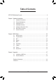
Table of Contents X570 UD Motherboard Layout..........................................................................................4 Chapter 1 Hardware Installation......................................................................................5 1-1 1-2 1-3 1-4 1-5 1-6 1-7 Installation Precautions..................................................................................... 5 Product Specifications.......................................................................................
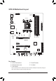
X570 UD Motherboard Layout KB_MS_USB SYS_FAN1 CPU_FAN ATX_12V CPU_OPT HDMI Socket AM4 R_USB30 ATX QFLED QFLASH_PLUS SYS_FAN2 USB30_LAN AUDIO PCIEX16 DDR4_B2 42 DDR4_B1 60 DDR4_A2 80 DDR4_A1 110 Realtek® GbE LAN M2A_SOCKET M_BIOS X570 UD SATA3 4 2 0 5 3 1 PCIEX1_1 AMD X570 CODEC PCIEX4_1 PCIEX1_2 BAT iTE® Super I/O PCIEX4_2 F_AUDIO CLR_CMOS LED_C1 TPM F_USB2 F_USB1 F_USB30_2 F_USB30_1 F_PANEL Box Contents 55 X570 UD motherboard 55 Motherboard driver disk 55 User's Manua
Chapter 1 1-1 Hardware Installation Installation Precautions The motherboard contains numerous delicate electronic circuits and components which can become damaged as a result of electrostatic discharge (ESD). Prior to installation, carefully read the user's manual and follow these procedures: •• Prior to installation, make sure the chassis is suitable for the motherboard. •• Prior to installation, do not remove or break motherboard S/N (Serial Number) sticker or warranty sticker provided by your dealer.
1-2 Product Specifications CPU Chipset AMD X570 Memory 3rd Generation AMD Ryzen™ processors: - Support for DDR4 3200/2933/2667/2400/2133 MHz memory modules 2nd Generation AMD Ryzen™ processors/2nd Generation AMD Ryzen™ with Radeon™ Vega Graphics processors/AMD Ryzen™ with Radeon™ Vega Graphics processors: - Support for DDR4 2933/2667/2400/2133 MHz memory modules 4 x DDR4 DIMM sockets supporting up to 128 GB (32 GB single DIMM capacity) of system memory Dual channel memory architectur
Multi-Graphics Support for AMD Quad-GPU CrossFire™ and 2-Way AMD CrossFire™ technologies Technology (Note 3) Storage Interface Integrated in the CPU: 3rd Generation AMD Ryzen™ processors: - 1 x M.2 connector (Socket 3, M key, type 2242/2260/2280/22110 SATA and PCIe 4.0 x4/x2 SSD support) 2nd Generation AMD Ryzen™ processors/2nd Generation AMD Ryzen™ with Radeon™ Vega Graphics processors/AMD Ryzen™ with Radeon™ Vega Graphics processors: - 1 x M.
Hardware Monitor BIOS Unique Features Voltage detection Temperature detection Fan speed detection Water cooling flow rate detection Overheating warning Fan fail warning Fan speed control * Whether the fan speed control function is supported will depend on the fan you install. 1 x 128 Mbit flash Use of licensed AMI UEFI BIOS PnP 1.0a, DMI 2.7, WfM 2.0, SM BIOS 2.7, ACPI 5.0 Support for APP Center * Available applications in APP Center may vary by motherboard model.
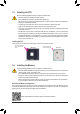
1-3 Installing the CPU Read the following guidelines before you begin to install the CPU: •• Make sure that the motherboard supports the CPU. (Go to GIGABYTE's website for the latest CPU support list.) •• Always turn off the computer and unplug the power cord from the power outlet before installing the CPU to prevent hardware damage. •• Locate the pin one of the CPU. The CPU cannot be inserted if oriented incorrectly. •• Apply an even and thin layer of thermal grease on the surface of the CPU.
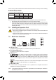
The four memory sockets are divided into two channels and each channel has two memory sockets as following: Channel A: DDR4_A1, DDR4_A2 Channel B: DDR4_B1, DDR4_B2 Dual Channel Memory Configurations Table 2 Modules 4 Modules DDR4_A1 DDR4_A2 DDR4_B1 DDR4_B2 -- DS/SS -- DS/SS DS/SS -- DS/SS -- DS/SS DS/SS DS/SS DS/SS (SS=Single-Sided, DS=Double-Sided, "- -"=No Memory) Due to CPU limitations, read the following guidelines before installing the memory in Dual Channel mode. 1.
USB 3.2 Gen 1 Port (White) The USB 3.2 Gen 1 port supports the USB 3.2 Gen 1 specification and is compatible to the USB 2.0 specification. Use this port for USB devices. Before using Q-Flash Plus (Note 2), make sure to insert the USB flash drive into this port first. Q-Flash Plus Button (Note 2) This button allows you to update the BIOS when the power connector is connected but the system is not powered on.
1-7 Internal Connectors 4 1 5 3 2 4 8 15 7 14 10 6 13 12 11 9 1) ATX_12V 9) F_PANEL 2) ATX 10) F_AUDIO 3) CPU_FAN 11) F_USB30_1/F_USB30_2 4) SYS_FAN1/2 12) F_USB1/F_USB2 5) CPU_OPT 13) TPM 6) LED_C1 14) CLR_CMOS 7) SATA3 0/1/2/3/4/5 15) BAT 8) M2A_SOCKET Read the following guidelines before connecting external devices: •• First make sure your devices are compliant with the connectors you wish to connect.
1/2) ATX_12V/ATX (2x4 12V Power Connector and 2x12 Main Power Connector) With the use of the power connector, the power supply can supply enough stable power to all the components on the motherboard. Before connecting the power connector, first make sure the power supply is turned off and all devices are properly installed. The power connector possesses a foolproof design. Connect the power supply cable to the power connector in the correct orientation.
3/4) CPU_FAN/SYS_FAN1/2 (Fan Headers) All fan headers on this motherboard are 4-pin. Most fan headers possess a foolproof insertion design. When connecting a fan cable, be sure to connect it in the correct orientation (the black connector wire is the ground wire). The speed control function requires the use of a fan with fan speed control design. For optimum heat dissipation, it is recommended that a system fan be installed inside the chassis. Pin No.
S B_ B S S _ S S_ _ B 7) SATA3 0/1/2/3/4/5 (SATA 6Gb/s Connectors) The SATA connectors conform to SATA 6Gb/s standard and are compatible with SATA 3Gb/s and SATA 1.5Gb/s standard. Each SATA connector supports a single SATA device. The SATA connectors support RAID 0, RAID 1, and RAID 10. Refer to Chapter 3, "Configuring a RAID Set," for instructions on configuring a RAID array. _ U _ B F SATA3 SB3 F 4 5 G.QBOFM 2 0 3 1 G.QBOFM 7 1 7 1 _0 S _ G.QBOFM Pin No.
9) F_PANEL (Front Panel Header) PWR_LED+ PWR_LEDPWR_LED- HD+ HDRESRES+ CICI+ SPEAK+ NC NC SPEAK- PLED+ PLEDPW+ PW- Connect the power switch, reset switch, speaker, chassis intrusion switch/sensor and system status indicator on the chassis to this header according to the pin assignments below. Note the positive and negative pins before connecting the cables.
1 1 S B SS 1 S U 2 3 S 1 S F_ S F G.QBOFM B SS 11) F_USB30_1/F_USB30_2 (USB 3.2 Gen 1 Headers) 20 11 B Definition D1D1+ NC D2+ D2GND SSTX2+ Pin No. 15 16 17 18 19 20 Definition SSTX2GND SSRX2+ SSRX2VBUS No Pin S _ B Pin No. 8 9 10 11 12 13 14 B S_ _ 10 Definition VBUS SSRX1SSRX1+ GND SSTX1SSTX1+ GND 3 1 Pin No. 1 2 3 4 5 6 7 S B_ F_ U S The headers conform to USB 3.2 Gen 1 and USB 2.0 specification and each header can provide two USB ports. For purchasing the optional 3.
14) CLR_CMOS (Clear CMOS Jumper) Use this jumper to clear the BIOS configuration and reset the CMOS values to factory defaults. To clear the CMOS values, use a metal object like a screwdriver to touch the two pins for a few seconds. Open: Normal Short: Clear CMOS Values •• Always turn off your computer and unplug the power cord from the power outlet before clearing the CMOS values.
Chapter 2 BIOS Setup BIOS (Basic Input and Output System) records hardware parameters of the system in the CMOS on the motherboard. Its major functions include conducting the Power-On Self-Test (POST) during system startup, saving system parameters and loading operating system, etc. BIOS includes a BIOS Setup program that allows the user to modify basic system configuration settings or to activate certain system features.
2-2 The Main Menu System Time Setup Menus Hardware Information Configuration Items Current Settings Quick Access Bar allows you to enter Easy Mode, select BIOS default language, configure fan settings, or enter Q-Flash.
2-3 M.I.T. Whether the system will work stably with the overclock/overvoltage settings you made is dependent on your overall system configurations. Incorrectly doing overclock/overvoltage may result in damage to CPU, chipset, or memory and reduce the useful life of these components. This page is for advanced users only and we recommend you not to alter the default settings to prevent system instability or other unexpected results. (Inadequately altering the settings may result in system's failure to boot.
`` Advanced CPU Core Settings && CPU Clock Ratio, CPU Frequency The settings above are synchronous to those under the same items on the Advanced Frequency Settings menu. && Core Performance Boost (Note 1) Allows you to determine whether to enable the Core Performance Boost (CPB) technology, a CPU performance-boost technology.
`` Advanced Memory Settings && Extreme Memory Profile (X.M.P.) (Note), System Memory Multiplier, Memory Frequency(MHz) The settings above are synchronous to those under the same items on the Advanced Frequency Settings menu. && XMP High Frequency Support (Note) Allows you to select the compatibility level for high-frequency memory. This item is configurable only when Extreme Memory Profile (X.M.P.) is set to Profile1 or Profile2.
`` Smart Fan 5 && Monitor Allows you to select a target to monitor and to make further adjustment. (Default: CPU FAN) && Fan Speed Control Allows you to determine whether to enable the fan speed control function and adjust the fan speed. Normal Allows the fan to run at different speeds according to the temperature. You can adjust the fan speed with System Information Viewer based on your system requirements. (Default) Silent Allows the fan to run at slow speeds.
2-4 System This section provides information on your motherboard model and BIOS version. You can also select the default language used by the BIOS and manually set the system time. && System Language Selects the default language used by the BIOS. && System Date Sets the system date. The date format is week (read-only), month, date, and year. Use to switch between the Month, Date, and Year fields and use the or key to set the desired value.
2-5 BIOS && Boot Option Priorities Specifies the overall boot order from the available devices. Removable storage devices that support GPT format will be prefixed with "UEFI:" string on the boot device list. To boot from an operating system that supports GPT partitioning, select the device prefixed with "UEFI:" string.
&& SATA Support Last Boot SATA Devices Only Except for the previous boot drive, all SATA devices are disabled before the OS boot process completes. (Default) All SATA Devices All SATA devices are functional in the operating system and during the POST. This item is configurable only when Fast Boot is set to Enabled or Ultra Fast. && NVMe Support Allows you to enable or disable NVMe device(s). (Default: Enabled) This item is configurable only when Fast Boot is set to Enabled or Ultra Fast.
&& Other PCI Device ROM Priority Allows you to select whether to enable the UEFI or Legacy option ROM for the PCI device controller other than the LAN, storage device, and graphics controllers. Disabled Disables option ROM. UEFI Only Enables UEFI option ROM only. (Default) Legacy Only Enables legacy option ROM only. This item is configurable only when CSM Support is set to Enabled. && Administrator Password Allows you to configure an administrator password.
2-6 Peripherals && AMD CPU fTPM Enables or disables the TPM 2.0 function integrated in the AMD CPU. (Default: Disabled) && Initial Display Output Specifies the first initiation of the monitor display from the installed PCI Express graphics card or the onboard graphics. IGD Video (Note) Sets the onboard graphics as the first display. PCIe 1 Slot Sets the graphics card on the PCIEX16 slot as the first display.
`` Trusted Computing Enables or disables Trusted Platform Module (TPM). `` USB Configuration && Legacy USB Support Allows USB keyboard/mouse to be used in MS-DOS. (Default: Enabled) && XHCI Hand-off Determines whether to enable XHCI Hand-off feature for an operating system without XHCI Hand-off support. (Default: Enabled) && USB Mass Storage Driver Support Enables or disables support for USB storage devices.
`` AMD CBS This sub-menu provides AMD CBS-related configuration options. `` Realtek PCIe GBE Family Controller This sub-menu provides information on LAN configuration and related configuration options.
2-7 Chipset && IOMMU Enables or disables AMD IOMMU support. (Default: Auto) && PCIEX16 Bifurcation Allows you to determine how the bandwidth of the PCIEX16 slot is divided. Options: Auto, PCIE 2x8, PCIE 1x8/2x4, PCIE 4x4. (Default: Auto) && SATA Mode Enables or disables RAID for the integrated SATA controllers or configures the SATA controllers to AHCI mode. RAID Enables RAID for the SATA controller. AHCI Configures the SATA controllers to AHCI mode.
2-8 Power && AC BACK Determines the state of the system after the return of power from an AC power loss. Memory The system returns to its last known awake state upon the return of the AC power. Always On The system is turned on upon the return of the AC power. Always Off The system stays off upon the return of the AC power. (Default) && Power On By Keyboard Allows the system to be turned on by a PS/2 keyboard wake-up event.
&& ErP Determines whether to let the system consume least power in S5 (shutdown) state. Note: When this item is set to Enabled, the following functions will become unavailable: Resume by Alarm, power on by mouse, and power on by keyboard. && Soft-Off by PWR-BTTN Configures the way to turn off the computer in MS-DOS mode using the power button. Instant-Off Press the power button and then the system will be turned off instantly. (Default) Delay 4 Sec.
2-9 Save & Exit && Save & Exit Setup Press on this item and select Yes. This saves the changes to the CMOS and exits the BIOS Setup program. Select No or press to return to the BIOS Setup Main Menu. && Exit Without Saving Press on this item and select Yes. This exits the BIOS Setup without saving the changes made in BIOS Setup to the CMOS. Select No or press to return to the BIOS Setup Main Menu.
Chapter 3 3-1 Appendix Configuring a RAID Set RAID Levels Minimum Number of Hard Drives Array Capacity Fault Tolerance RAID 0 ≥2 Number of hard drives * Size of the smallest drive No RAID 1 2 RAID 10 4 Size of the smallest drive (Number of hard drives/2) * Size of the smallest drive Yes Yes Before you begin, please prepare the following items: •• At least two SATA hard drives or SSDs.
C. UEFI RAID Configuration Steps: 1. In BIOS Setup, go to BIOS and set CSM Support to Disabled. Save the changes and exit BIOS Setup. 2. After the system reboot, enter BIOS Setup again. Then enter the Peripherals\RAIDXpert2 Configuration Utility sub-menu. 3. On the RAIDXpert2 Configuration Utility screen, press on Array Management to enter the Create Array screen. Then, select a RAID level.
3-2 Drivers Installation •• Before installing the drivers, first install the operating system. •• After installing the operating system, insert the motherboard driver disk into your optical drive. Click on the message "Tap to choose what happens with this disc" on the top-right corner of the screen and select "Run Run.exe." (Or go to My Computer, double-click the optical drive and execute the Run.exe program.
Regulatory Statements Regulatory Notices This document must not be copied without our written permission, and the contents there of must not be imparted to a third party nor be used for any unauthorized purpose. Contravention will be prosecuted. We believe that the information contained herein was accurate in all respects at the time of printing. GIGABYTE cannot, however, assume any responsibility for errors or omissions in this text.
FCC Notice (U.S.A. Only) This equipment has been tested and found to comply with the limits for a Class B digital device, pursuant to Part 15 of the FCC Rules. These limits are designed to provide reasonable protection against harmful interference in a residential installation. This equipment generates, uses, and can radiate radio frequency energy and, if not installed and used in accordance with the instructions, may cause harmful interference to radio communications.
- 41 -
- 42 -
- 43 -
Contact Us GIGA-BYTE TECHNOLOGY CO., LTD. Address: No.6, Baoqiang Rd., Xindian Dist., New Taipei City 231, Taiwan TEL: +886-2-8912-4000, FAX: +886-2-8912-4005 Tech. and Non-Tech. Support (Sales/Marketing) : https://esupport.gigabyte.com WEB address (English): https://www.gigabyte.com WEB address (Chinese): https://www.gigabyte.com/tw •• GIGABYTE eSupport To submit a technical or non-technical (Sales/Marketing) question, please link to: https://esupport.gigabyte.