Z490I AORUS ULTRA User's Manual Rev. 1001 12ME-Z49ARSI-1001R For more product details, please visit GIGABYTE's website. To reduce the impacts on global warming, the packaging materials of this product are recyclable and reusable. GIGABYTE works with you to protect the environment.
Copyright © 2020 GIGA-BYTE TECHNOLOGY CO., LTD. All rights reserved. The trademarks mentioned in this manual are legally registered to their respective owners. Disclaimer Information in this manual is protected by copyright laws and is the property of GIGABYTE. Changes to the specifications and features in this manual may be made by GIGABYTE without prior notice.
Table of Contents Z490I AORUS ULTRA Motherboard Layout.....................................................................4 Z490I AORUS ULTRA Motherboard Block Diagram.........................................................5 Chapter 1 Hardware Installation......................................................................................6 1-1 1-2 1-3 1-4 1-5 1-6 1-7 Installation Precautions..................................................................................... 6 Product Specifications...
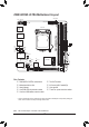
Z490I AORUS ULTRA Motherboard Layout SYS_FAN2 ATX_12V_2X4 SYS_FAN3 D_LED AUDIO 60 80 (Note) Intel® Z490 60 (Note) M_BIOS F_AUDIO SPEAKER 80 iTE® Super I/O PCIEX16 CI CODEC USB 2.
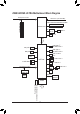
Z490I AORUS ULTRA Motherboard Block Diagram PCI Express 3.0 Bus CPU CLK+/- (100~500 MHz) x16 1 PCI Express x16 DDR4 3200/2933/2666/2400/2133 MHz LGA1200 CPU DDI PARADE PS175 HDMI 2.0 DP 1.4 DMI 3.0 DDI 1 USB Type-C™, with USB 3.2 Gen 1 M2A_CPU 1 USB Type-C™, with USB 3.2 Gen 2 M2M_SB 1 USB 3.2 Gen 2 M.2 CNVi WIFI Type A 6 USB 3.2 Gen 1 Intel® Z490 4 SATA 6Gb/s 2 USB 2.0/1.1 PCI Express 3.0 Bus USB 2.0 Hub x1 Intel® 2.
Chapter 1 1-1 Hardware Installation Installation Precautions The motherboard contains numerous delicate electronic circuits and components which can become damaged as a result of electrostatic discharge (ESD). Prior to installation, carefully read the user's manual and follow these procedures: •• Prior to installation, make sure the chassis is suitable for the motherboard. •• Prior to installation, do not remove or break motherboard S/N (Serial Number) sticker or warranty sticker provided by your dealer.
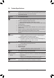
1-2 Product Specifications CPU Support for 10th Generation Intel® Core™ i9 processors/Intel® Core™ i7 processors/ Intel® Core™ i5 processors/Intel® Core™ i3 processors/Intel® Pentium® processors/ Intel® Celeron® processors in the LGA1200 package L3 cache varies with CPU Chipset Intel® Z490 Express Chipset Memory Intel® Core™ i9/i7 processors: - Support for DDR4 3200/3000/2933/2666/2400/2133 MHz memory modules Intel® Core™ i5/i3/Pentium®/Celeron® processors: - Support for DDR4 2666/2400/
Storage Interface 1 x M.2 connector (Socket 3, M key, type 2260/2280 SATA and PCIe x4/x2 SSD support) (M2A_CPU) 1 x M.2 connector on the back of the motherboard (Socket 3, M key, type 2260/2280 SATA and PCIe x4/x2 SSD support) (M2M_SB) 4 x SATA 6Gb/s connectors Support for RAID 0, RAID 1, RAID 5, and RAID 10 * Refer to "1-7 Internal Connectors," for the installation notices for the M.2 and SATA connectors.
Hardware Monitor BIOS Unique Features Bundled Software Operating System Voltage detection Temperature detection Fan speed detection Overheating warning Fan fail warning Fan speed control * Whether the fan speed control function is supported will depend on the cooler you install. 1 x 256 Mbit flash Use of licensed AMI UEFI BIOS PnP 1.0a, DMI 2.7, WfM 2.0, SM BIOS 2.7, ACPI 5.
1-3 Installing the CPU Read the following guidelines before you begin to install the CPU: •• Make sure that the motherboard supports the CPU. (Go to GIGABYTE's website for the latest CPU support list.) •• Always turn off the computer and unplug the power cord from the power outlet before installing the CPU to prevent hardware damage. •• Locate the pin one of the CPU. The CPU cannot be inserted if oriented incorrectly.
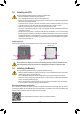
The two memory sockets are divided into two channels and each channel has one memory socket as following: Channel A: DDR4_A1 Channel B: DDR4_B1 Due to CPU limitations, read the following guidelines before installing the memory in Dual Channel mode. 1. Dual Channel mode cannot be enabled if only one memory module is installed. 2. When enabling Dual Channel mode with two memory modules, it is recommended that memory of the same capacity, brand, speed, and chips be used.
HDMI Port The HDMI port supports HDCP 2.3 and Dolby TrueHD and DTS HD Master Audio formats. It also supports up to 192KHz/16bit 7.1-channel LPCM audio output. You can use this port to connect your HDMI-supported monitor. The maximum supported resolution is 4096x2160@60 Hz, but the actual resolutions supported are dependent on the monitor being used. After installing the HDMI/DisplayPort device, make sure to set the default sound playback device to HDMI/DisplayPort.
1-7 Internal Connectors 2 4 3 1 7 6 12 11 16 17 5 14 9 15 8 10 13 1) ATX_12V_2X4 10) F_PANEL 2) ATX 11) SPEAKER 3) CPU_FAN 12) F_U32 4) SYS_FAN1/2/3 13) F_USB30C_1 5) D_LED 14) F_USB 6) LED_C 15) CI 7) SATA3 0/1/2/3 16) CLR_CMOS 8) M2A_CPU/M2M_SB (Note) 17) BAT 9) F_AUDIO (Note) The M2M_SB connector is on the back of the motherboard.
1/2) ATX_12V_2X4/ATX (2x4 12V Power Connector and 2x12 Main Power Connector) With the use of the power connector, the power supply can supply enough stable power to all the components on the motherboard. Before connecting the power connector, first make sure the power supply is turned off and all devices are properly installed. The power connector possesses a foolproof design. Connect the power supply cable to the power connector in the correct orientation.
5) D_LED (Addressable LED Strip Header) The header can be used to connect a standard 5050 addressable LED strip, with maximum power rating of 5A (5V) and maximum number of 1000 LEDs. Pin No. 1 2 3 4 B_ Connect your addressable LED strip to the header. The power pin (marked with a triangle on the plug) of the LED strip must be connected to Pin 1 of the addressable LED strip header. Incorrect connection may lead to the damage of the LED strip.
DEBUG PORT 7) SATA3 0/1/2/3 (SATA 6Gb/s Connectors) The SATA connectors conform to SATA 6Gb/s standard and are compatible with SATA 3Gb/s and SATA 1.5Gb/s standard. EachF SATA connector supports a single SATA device. The Intel® Chipset supports RAID 0, RAID 1, RAID 5, and RAID 10. Refer to Chapter 3, "Configuring a RAID Set," for instructions on configuring a RAID array. 1 Pin No.
Installation Notices for the M.2 and SATA Connectors: The availability of the SATA connectors may be affected by the type of device installed in the M.2 sockets. The M2A_CPU connector shares bandwidth with the SATA3 1 connector. Refer to the following table for details. •• M2A_CPU: Connector SATA3 0 SATA3 1 SATA3 2 SATA3 3 M.2 SATA SSD a r a a M.2 PCIe SSD a a a a No M.2 SSD Installed a a a a SATA3 0 SATA3 1 SATA3 2 SATA3 3 a a a a M.2 PCIe SSD a a a a No M.
10) F_PANEL (Front Panel Header) Connect the power switch, reset switch, and system status indicator on the chassis to this header according to the pin assignments below. Note the positive and negative pins before connecting the cables. Hard Drive Activity LED Reset Switch 1 2 HD+ HDRESRES+ NC •• PLED (Power LED): System Status LED S0 On S3/S4/S5 Off PLED+ PLEDPW+ PW- Power LED Power Switch 9 10 Connects to the power status indicator on the chassis front panel.
_0 F_USB30 F_ U F F_ F 12) F_U32 (USB 3.2 Gen 1 Header) S F_ The header conforms to USB 3.2 Gen 1 and USB 2.0 specification and can provide two USB ports. For purchasing the optional 3.5" front panel that provides two USB 3.2 Gen 1 ports, please contact the local dealer. 10 Pin No. 1 2 3 B_ 4 5 6 7 Definition VBUS SSRX1SSRX1+ GND SSTX1SSTX1+ GND Pin No. 8 9 10 B 11 12 13 14 Definition D1D1+ NC SS D2+ D2GND SSTX2+ Pin No.
15) CI (Chassis Intrusion Header) This motherboard provides a chassis detection feature that detects if the chassis cover has been removed. This function requires a chassis with chassis intrusion detection design. Pin No. 1 2 1 Definition Signal GND S S S U _ _ _ 16) CLR_CMOS (Clear CMOS Jumper) S S S U Use this jumper to clear the BIOS configuration and reset the CMOS values to factory defaults.
Chapter 2 BIOS Setup BIOS (Basic Input and Output System) records hardware parameters of the system in the CMOS on the motherboard. Its major functions include conducting the Power-On Self-Test (POST) during system startup, saving system parameters and loading operating system, etc. BIOS includes a BIOS Setup program that allows the user to modify basic system configuration settings or to activate certain system features.
2-2 The Main Menu System Time Setup Menus Configuration Items Hardware Information Option Description Current Settings Quick Access Bar allows you to quickly move to the General Help, Easy Mode, Smart Fan 5, or Q-Flash screen.
2-3 Favorites (F11) Set your frequently used options as your favorites and use the key to quickly switch to the page where all of your favorite options are located. To add or remove a favorite option, go to its original page and press on the option. The option is marked with a star sign if set as a "favorite.
2-4 Tweaker Whether the system will work stably with the overclock/overvoltage settings you made is dependent on your overall system configurations. Incorrectly doing overclock/overvoltage may result in damage to CPU, chipset, or memory and reduce the useful life of these components. This page is for advanced users only and we recommend you not to alter the default settings to prevent system instability or other unexpected results.
&& FCLK Frequency for Early Power On Allows you to set the FCLK frequency. Options are: Normal(800Mhz), 1GHz, 400MHz. (Default: 1GHz) && Hyper-Threading Technology Allows you to determine whether to enable multi-threading technology when using an Intel® CPU that supports this function. This feature only works for operating systems that support multi-processor mode. Auto lets the BIOS automatically configure this setting. (Default: Auto) && No.
&& Frequency Clipping TVB (Note) Allows you to enable or disable automatic CPU frequency reduction initiated by Thermal Velocity Boost. Auto lets the BIOS automatically configure this setting. (Default: Auto) && Voltage reduction initiated TVB (Note) Allows you to enable or disable automatic CPU voltage reduction initiated by Thermal Velocity Boost. Auto lets the BIOS automatically configure this setting.
&& Package Power Limit TDP (Watts) / Package Power Limit Time Allows you to set the power limit for CPU Turbo mode and how long it takes to operate at the specified power limit. If the specified value is exceeded, the CPU will automatically reduce the core frequency in order to reduce the power. Auto sets the power limit according to the CPU specifications. This item is configurable only when Turbo Power Limits is set to Enabled.
&& Memory Boot Mode Provides memory detection and training methods. Auto Lets the BIOS automatically configure this setting. (Default) Normal The BIOS automatically performs memory training. Please note that if the system becomes unstable or unbootable, try to clear the CMOS values and reset the board to default values. (Refer to the introductions of the battery/clear CMOS jumper in Chapter 1 for how to clear the CMOS values.
2-5 Settings Platform Power && Platform Power Management Enables or disables the Active State Power Management function (ASPM). (Default: Disabled) && PEG ASPM Allows you to configure the ASPM mode for the device connected to the CPU PEG bus. This item is configurable only when Platform Power Management is set to Enabled. (Default: Disabled) && PCH ASPM Allows you to configure the ASPM mode for the device connected to Chipset's PCI Express bus.
&& RC6(Render Standby) Allows you to determine whether to let the onboard graphics enter standby mode to decrease power consumption. (Default: Enabled) && AC BACK Determines the state of the system after the return of power from an AC power loss. Memory The system returns to its last known awake state upon the return of the AC power. Always On The system is turned on upon the return of the AC power. Always Off The system stays off upon the return of the AC power.
USB Configuration && Legacy USB Support Allows USB keyboard/mouse to be used in MS-DOS. (Default: Enabled) && XHCI Hand-off Determines whether to enable XHCI Hand-off feature for an operating system without XHCI Hand-off support. (Default: Enabled) && USB Mass Storage Driver Support Enables or disables support for USB storage devices. (Default: Enabled) && Mass Storage Devices Displays a list of connected USB mass storage devices. This item appears only when a USB storage device is installed.
&& Port 0/1/2/3 Enables or disables each SATA port. (Default: Enabled) && Hot plug Enables or disable the hot plug capability for each SATA port. (Default: Disabled) && Configured as eSATA Enables or disables support for external SATA devices. EZ RAID Allows you to quickly set up a RAID array. Refer to Chapter 3, "Configuring a RAID Set," for instructions on configuring a RAID array.
PC Health Status && Reset Case Open Status Disabled Keeps or clears the record of previous chassis intrusion status. (Default) Enabled Clears the record of previous chassis intrusion status and the Case Open field will show "No" at next boot. && Case Open Displays the detection status of the chassis intrusion detection device attached to the motherboard CI header. If the system chassis cover is removed, this field will show "Yes", otherwise it will show "No".
2-6 System Info. This section provides information on your motherboard model and BIOS version. You can also select the default language used by the BIOS and manually set the system time. && Access Level Displays the current access level depending on the type of password protection used. (If no password is set, the default will display as Administrator.
2-7 Boot && Bootup NumLock State Enables or disables Numlock feature on the numeric keypad of the keyboard after the POST. (Default: On) && Security Option Specifies whether a password is required every time the system boots, or only when you enter BIOS Setup. After configuring this item, set the password(s) under the Administrator Password/User Password item. Setup A password is only required for entering the BIOS Setup program.
&& USB Support Disabled All USB devices are disabled before the OS boot process completes. Full Initial All USB devices are functional in the operating system and during the POST. (Default) Partial Initial Part of the USB devices are disabled before the OS boot process completes. This item is configurable only when Fast Boot is set to Enabled or Ultra Fast. This function is disabled when Fast Boot is set to Ultra Fast.
&& Administrator Password Allows you to configure an administrator password. Press on this item, type the password, and then press . You will be requested to confirm the password. Type the password again and press . You must enter the administrator password (or user password) at system startup and when entering BIOS Setup. Differing from the user password, the administrator password allows you to make changes to all BIOS settings.
2-8 Save & Exit && Save & Exit Setup Press on this item and select Yes. This saves the changes to the CMOS and exits the BIOS Setup program. Select No or press to return to the BIOS Setup Main Menu. && Exit Without Saving Press on this item and select Yes. This exits the BIOS Setup without saving the changes made in BIOS Setup to the CMOS. Select No or press to return to the BIOS Setup Main Menu.
Chapter 3 3-1 Appendix Configuring a RAID Set RAID Levels Minimum Number of Hard Drives Array Capacity Fault Tolerance RAID 0 RAID 1 RAID 5 RAID 10 ≥2 2 ≥3 4 Number of hard drives * Size of the smallest drive No Size of the smallest drive (Number of hard drives -1) * Size of the smallest drive Yes (Number of hard drives/2) * Size of the smallest drive Yes Yes Before you begin, please prepare the following items: •• At least two SATA hard drives or SSDs.
3. After completing, you'll be brought back to the Intel(R) Rapid Storage Technology screen. Under RAID Volumes you can see the new RAID volume. To see more detailed information, press on the volume to check for information on RAID level, stripe block size, array name, and array capacity, etc. C-2. UEFI RAID Configuration Steps: 1. In BIOS Setup, go to Boot and set CSM Support to Disabled. Save the changes and exit BIOS Setup. 2. After the system reboot, enter BIOS Setup again.
Install the SATA RAID/AHCI driver and operating system With the correct BIOS settings, you are ready to install the operating system. Installing the Operating System As some operating systems already include Intel® RAID/AHCI driver, you do not need to install separate RAID/ AHCI driver during the Windows installation process.
A-2: Installation in Intel RST Premium With Intel Optane System Acceleration mode If the SATA controller has been configured in Intel RST Premium With Intel Optane System Acceleration mode, please follow the steps below: 1. After system restarts, go to the BIOS Setup, make sure CSM Support under the Boot menu is disabled. 2. Go to Settings\IO Ports\SATA And RST Configuration and make sure USE RST Legacy OROM is disabled and RST Control PCIe Storage Devices is set to Manual.
3-3 Drivers Installation •• Before installing the drivers, first install the operating system. •• After installing the operating system, insert the motherboard driver disc into your optical drive. Click on the message "Tap to choose what happens with this disc" on the top-right corner of the screen and select "Run Run.exe." (Or go to My Computer, double-click the optical drive and execute the Run.exe program.
Regulatory Notices CAUTION: The manufacturer is not responsible for any interference caused by unauthorized modifications and/or use of unauthorized antennas. Such changes and/or modifications not expressly approved by the party responsible for compliance of this device could void the user's authority to operate the equipment.
Radiation Exposure Statement: Under Industry Canada regulations, this radio transmitter may only operate using an antenna of a type and maximum (or lesser) gain approved for the transmitter by Industry Canada. To reduce potential radio interference to other users, the antenna type and its gain should be so chosen that the equivalent isotopically radiated power (e.i.r.p.) is not more than that necessary for successful communication.
European Community Directive RED Directive Compliance Statement: This equipment is suitable for home and office use in all the European Community Member States and EFTA Member States. The low band 5.15 -5.
- 47 -
Contact Us GIGA-BYTE TECHNOLOGY CO., LTD. Address: No.6, Baoqiang Rd., Xindian Dist., New Taipei City 231, Taiwan TEL: +886-2-8912-4000, FAX: +886-2-8912-4005 Tech. and Non-Tech. Support (Sales/Marketing) : https://esupport.gigabyte.com WEB address (English): https://www.gigabyte.com WEB address (Chinese): https://www.gigabyte.com/tw •• GIGABYTE eSupport To submit a technical or non-technical (Sales/Marketing) question, please link to: https://esupport.gigabyte.