
User manual

Digital High Frequency Analyser HF58B-r
© Gigahertz Solutions GmbH, 90579 Langenzenn, Germany Revision 4.5 (Febuary 2006) Page 10
Quantitative Measurement:
Special Case 2: Radar
For air and sea navigation a radar antenna
slowly rotates around its own axis, thereby
emitting a tightly bundled “radar ray“. Even
with sufficient signal strength, this ray can
only be detected every couple of seconds,
for a few milliseconds. This requires special
measurement technology.
The HF58B-r with its video bandwidth of 2
MHz provides this technology. Please use
the following procedure to ensure correct
readings:
Setting: Video bandwidth to “Tpmax”. Signal
Evaluation – “Peak”. With the help of the au-
dio analysis (a very short “Beep” every cou-
ple of seconds), one can clearly identify a
radar signal. With this setting and the LogPer
antenna you can identify the direction of the
source of the signal.
With the signal Evaluation switch set to
“Peak Hold” and the LogPer antenna di-
rected towards the signal emitting source.
Wait for several circles of the radar ray, move
the instrument a little left and right in order to
get the relevant maximum reading.
The long delays between pulses may con-
sume a great deal of time trying to detect
signal direction with a LogPer aerial.
Please note that there are Radar systems
that are operated at even higher frequencies
that can be measured with this instrument,
yet possibly not the full intensity.
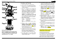
Quantitative Measurement:
Identify where the radiation enters a struc-
ture
As a first step eliminate sources from within
the same room (e.g. cordless phones, wire-
less routers, etc.) Once this is completed, the
remaining radiation will originate from out-
side. For remedial shielding it is important to
identify those areas of all walls (including
doors, windows and window frames!), ceiling
and floor, which are penetrated by the radia-
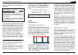
tion. To do this one should not
stand in the
centre of the room, measuring in all direc-
tions from there, but monitor the permeable
areas with the antenna (LogPer) directed and
positioned close to the wall
7
. That is because
the antenna lobe widens with increasing fre-
quency. In addition reflections and cancella-
tions inside rooms make it difficult and often
impossible to locate the “leaks” accurately.
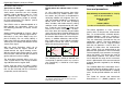
See the illustrating sketch below!
wall
antenna
wall
antenna
potentiell
durchlässiger
Bereich
wrong!
right!
potentially HF-permeable
part of the wall
The uncertainty of localization with HF-antennas
The shielding itself should be defined and
surveyed by a specialist and in any case the
area covered by it should be much larger
than the leak
7
Please note: In this position the readings on the LCD
only indicate relative highs and lows that cannot be
interpreted in absolute terms.
Limiting values, recommenda-
tions and precautions
Precautionary recommentation for sleeping
areas for pulsed radiation
Below 0.1 µW/m²
(SBM 2003)
below 1 µW/m²
(Landessanitätsdirektion Salzburg, Austria)
The official regulations in many countries
specify limits far beyond the recommenda-
tions of environmentally oriented doctors,
“building biologists” and many scientific in-
stitutions and also those of other countries.
They are vehemently criticised, but they are
nonetheless “official”. The limits depend on
frequencies and in the HF range of interest
here they are between 4 and 10 W/m², far
beyond 10 million times the recommenda-
tions. Official limits are determined by the
potential heat generation in the human body
and consequently measurements of averages
rather than peaks. This ignores the state of
environmental medicine. The “official” limits
are far beyond the range of this instrument,
which is optimized for accurate measurement
of power densities targeted by the building
biologists.
The standard SBM 2003 cited above classi-
fies power densities of below 1µW/m² as “no
anomaly” for non pulsed radiation in sleeping
areas, and for pulsed radiation one tenth of
that.
The "Bund für Umwelt und Naturschutz
Deutschland e. V." (BUND) proposes 100