
User manual
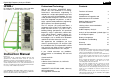

Digital High Frequency Analyser HF58B-r
© Gigahertz Solutions GmbH, 90579 Langenzenn, Germany Revision 4.5 (Febuary 2006) Page 2
English printwork to follow!
The HF component of the testing instru-
ment is shielded against interference by
an internal metal box at the antenna input
(shielding factor ca. 35 – 40 dB)
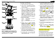
Functions and Controls
1) Volume control for the audio analysis.
2) Jack, 3.5 mm : AC output for the modu-
lated part of the signal, for Audio analysis
via PC or headset.
3) Jack, 12 – 15 Volt DC for charging the
battery. AC adapter for 230 Volt/50 Hz
and 60 Hz is included. For other Volt-
ages/Frequencies please get an equiva-
lent local AC adaptor with the output pa-
rameters 12 – 15 Volt DC / >100mA.
Caution: If an alkaline battery is used,
under no circumstances should the
power adapter be connected at the same
time, otherwise the battery may explode.
4) Measurement ranges
coarse = 19.99 mW/m²
(=19 990µW/m²)
medium = 199.9 µW/m²
fine = 19.99 µW/m²
Scaling with external amplifier or damper is differ-
ent!
5) Selector switch for signal evaluation.
Standard setting: “Peak”. In peak hold
mode you can choose a time setting for
the droop rate (Standard = Slow) With
the push button (pos. 13 ) you can manu-
ally reset the peak hold value.
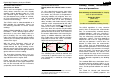
6) A little bar on the very left of the LCD in-
dicates the unit of the numerical reading:
bar on top = mW/m² (Milliwatts/m²)
bar on bottom = uW/m² (Microwatts/m²)
7) DC output, allows you to connect addi-
tional instruments, e.g. data logging de-
vices(1 VDC full scale).
8) Connecting socket for antenna cable. The
antenna is inserted into the “cross like”
opening at the front tip of the instrument.
9) Power Level Adapter Switch for external
optional amplifier or attenuator only. For
regular use of the instrument the switch
should be in pos. “0 dB“. (Any other position
will shift the decimal point to an incorrect position.)
10) ON/OFF switch. In middle switch-
position . . .., the audio analysis mode
is activated. In upper position
. set-
ting, you can additionally hear a signal
similar to a “Geiger counter”, propor-
tional to the field strength
1
.
11) Signal fraction: In mode “Full“, the total
signal strength is displayed. In “Pulse”
mode, only the pulsed / amplitude modu-
lated part of the signal is displayed.
12) This instrument has an “Auto-Power-Off
function“ to avoid unintentional discharge
of the battery
2
.
13) Push button to reset peak hold.
(Push and
hold for 2 seconds or until the readings do not fur-
ther decrease )
14) Switch for choosing the Video Band-
width for the LF-Signal processing.
Standard setting: “TP30MHz”
Typical default settings of major functions are
marked yellow in the text above.
1
For this feature the volume control should be turned
down completely because otherwise the sound mixes
with the “audio analysis”. Similar to Geiger counter.
2
The instrument switches off after about 30 Minutes at
regular charging level of the battery and after about 3
Minutes when “Low Batt.” is displayed on the LCD.