MDE-4199 Contactless Smart Card Retrofit Kit M05205K00X Installation Manual January 2005 Introduction Table of Contents Topic Page "Introduction" Page 1 "Table of Contents" Page 1 "Purpose" Page 1 "Required Reading" Page 2 "Related Documents" Page 2 "Required Tools" Page 2 "Parts Lists" Page 3 "Important Safety Information" Page 5 "Installation" Page 7 "Installing M05205K001 Kit in an Encore Unit" Page 7 "Installing M05205K002 Kit in an Eclipse Unit" Page 12 "Installing M05205K003
Introduction Required Reading Before installing this kit, the installer must read, understand, and follow: • this manual • NFPA 30A, The Automotive and Marine Service Station Code • NFPA 70, The National Electric Code • applicable federal, state and local codes and regulations Failure to do so may adversely affect the safe use and operation of the equipment. Note: This kit must be installed by a Gilbarco Authorized Service Contractor (ASC) to insure warranty.
Introduction Parts Lists The following tables provide the parts for the Contactless Smart Card Retrofit Kits. Encore Kit M05205K001 Description Part Number Quantities Assembly, Dual Head Card M03311A001 2 Cable, ESD Ground Card M02134A001 2 PCA, 13.
Introduction The Advantage Series Kit M05205K003 Using Space Reserved for Cash Acceptor Description Part Number Quantities Assembly, Dual Head Card M03311A001 2 Cable, ESD Ground Card M02134A001 2 PCA, 13.
Important Safety Information Important Safety Information This section introduces the hazards and safety precautions associated with installing, inspecting, maintaining or servicing this product. Before performing any task on this product, read this safety information and the applicable sections in this manual, where additional hazards and safety precautions for your task will be found.
Important Safety Information Emergency First Aid No Open Flames Open flames from matches, lighters, welding torches or other sources can ignite fuels and their vapors. No Sparks - No Smoking Sparks from starting vehicles, starting or using power tools, burning cigarettes, cigars or pipes can also ignite fuels and their vapors. Static electricity, including an electrostatic charge on your body, can cause a spark sufficient to ignite fuels and their vapors.
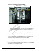
Installation Installation Installing M05205K001 Kit in an Encore Unit The M05205K001 Kit contains parts for both side 1 and side 2 of the Encore Unit. Therefore, all procedures performed on Side 1 of the unit must also be performed on Side 2. Removing the Card Reader from the Encore Unit When installing a contactless smart card kit, the existing card reader must be removed and replaced with a dual head card assembly (part of the kit).
Installation Figure 1: Rear View of Encore CIM Door With Card Reader Fasteners Cable Harness Connection Fasteners 7 Remove the four hex head screws (Figure 1) that secure the card reader bracket (Figure 1) and the card reader, to the options door using 1/4-inch nut driver. Dispose of the card reader and bracket. Note: Make note of the card readers’ gasket orientation, this information will be useful when installing the new M00682 card reader gasket.
Installation CAUTION A properly grounded electrostatic discharge wrist strap must be worn during this procedure. Failure to use electrostatic precautions may damage electronic components and void warranty.
Installation screw and lock washer that was removed in the previous step. 9 Ensure that all ground cables are secured to the unit with sufficient slack to prevent cable pulls and pinching.
Installation Installing the Antenna PCA The RF antenna must be located directly behind the area where the PayPass logo graphic is attached as shown in Figure 4. Figure 4: Encore CIM Door Showing Antenna PCA Location Front View PayPass Logo Location Rear View Mounting Holes 2 Pin Connector M05170A001 Antenna PCA Install the antenna as follows: 1 Locate the area where the antenna PCA will be mounted. 2 Using isopropyl alcohol, clean the mounting surface.
Installation Completing Installation for the Encore Units Perform the following steps to complete installation. 1 Close and secure the main doors. 2 Close and secure the CIM Doors 3 Install the appropriate graphics. 4 Restore power to unit. Refer to MDE-3893 Encore/Eclipse Owners Manual. 5 Upgrade the CRIND BIOS using the Laptop Tool Software. See MDE-3921 for complete instructions on loading the Laptop Tool Software.
Installation 5 Go to side 1 of the unit and open the Oven Door (Figure 5) on the CIM Door using the key provided with the dispenser. Figure 5: Eclipse CIM Door CIM Door Oven Door Key Location 6 Open the CIM Door by pushing down on the Slide Latch (Figure 6) located inside the unit.
Installation Figure 6: Eclipse Frame Assembly With CIM Door Removed Slide Latch Removing the Eclipse Existing Card Reader Perform the following procedures to remove the card reader. 1 From the rear of the CIM Door, disconnect the cable harness (Figure 7) from the card reader.
Installation Figure 7: Rear View of CIM Door with Card Reader Card Reader Cable Harness Card Reader Bracket Nuts Hold Assembly Together Nuts Hold Assembly to the CIM Door 2 Remove the four nuts that secure the card reader bracket and the card reader (Figure 7) to the CIM Door using a 9/32-inch nut driver. Discard the card reader. Retain the bracket and screws for reinstallation.
Installation CAUTION A properly grounded electrostatic discharge wrist strap must be worn during this procedure. Failure to use electrostatic precautions may damage electronic components and void warranty.
Installation 9 Ensure that the all Ground Cables are secured to the unit with sufficient slack to prevent cable pulls and pinching. Installing the Antenna PCA The RF antenna must be located directly behind the area where the logo graphic is attached. Looking at the back of the oven door, the antenna will be located on the right side just above the center of the door (to the right of the keypad). Install the antenna as follows: 1 Locate the area where the RF antenna will be mounted.
Installation Installing M05205K003 Kit in The Advantage Series Unit W/O Cash Acceptor The M05205K003 Kit contains parts for both side 1 and side 2 of The Advantage Series Unit with ADA Single Line or Monochrome Infoscreen. If both sides of the unit are being updated, all procedures performed on Side A of the unit must be performed on Side B also.
Installation Figure 10: Left Options Door Opened Card Reader Cable Clamp 9 Disconnect the data/power cable connection (Figure 11) from the card reader. Figure 11: Top View of Card Reader Mounted In Option Door Card Reader Bracket ESD Ground Connection Hex Head Fastener Hex Head Fastener Hex Head Fastener Data/Power Cable Connection Card Reader Gasket Lower Right Fan Screw 10 Using a cross-tip screwdriver, remove the screw that secures the ESD ground cable (Figure 11) to the option door chassis.
Installation 11 Using a 1/4-inch nut driver, remove the four hex head fasteners (Figure 11) that secure the card reader bracket (Figure 11) and the card reader to the options door. Dispose of the card reader. Note: Make note of the card reader’s gasket orientation. This information will be useful when installing the new M00682B001 Card Reader Gasket. Also, ensure that the option door surface has been cleaned with isopropyl alcohol and a clean cloth prior to installing the new card reader gasket.
Installation 5 Reconnect the power/data cable to the seven-pin connector (Figure 12) on the Printed Circuit Card (PCA) located on the left side of the dual head card assembly. CAUTION Refer to Figure 12 and ensure that the M02134A001 ESD Ground Cable is inserted into the correct connector on the dual head card assembly. Failure to connect the cable properly will damage the card reader.
Installation Figure 14: Advantage ESD Card Reader Ground Cable M02134A001 M02134A001 Cable 8 Ensure that the Ground Cable is secured to the unit with sufficient slack to prevent cable pulls and pinching. Use Q13558-04 Cable Mounts as required. Note: Installation of the PCA antenna will require positioning the antenna as shown in Figure 15. Using cloth and isopropyl alcohol, remove any dust or dirt from the antenna location prior to removing the adhesive backing from the PCA antenna.
Installation Figure 15: PCA Antenna Location Card Reader Cable To 2-Pin Connector On M03311A001 Dual Head Card Assembly M05170A001 PCA Antenna Antenna Mounting Holes CAUTION Refer to Figure 12 and ensure that the Antenna Cable is inserted into the 2 PIN Antenna connector on the dual head card assembly. Failure to connect the cable properly will damage the card reader.
Installation Perform the following procedures to upgrade CRIND BIOS. This upgrade is initiated by installing the U7 EPROM Integrated Circuit (IC), one per logic board, on CRIND logic board(s) T17764-XX according to the following steps. CAUTION A properly grounded ESD wrist strap must be worn during this procedure. Failure to use electrostatic precautions may damage electronic components and void warranty.
Installation Figure 17: T17764-XX CRIND Logic Board (-G3 Shown) Chip Orientation Notch U7 JP1-16 Figure 18: Grounded Chip Removal Tool Grounding Strap Chip Removal Tool MDE-4199 Contactless Smart Card Retrofit Kit M05205K00X Installation Manual • January 2005 Page 25
Installation 3 Install EPROM IC (one per logic board) at position U7, orienting notch on chip with indication mark on board as shown on Figure 17. 4 Install a jump jack on JP-11 (Figure 17) for each side of unit, as needed in order to Cold Start the unit. Note: Jumper on JP-11 informs the CRIND that a system Cold Start is present. 5 Restore power to the unit. Refer to MDE-2540 The Advantage, Legacy, and MPD Series Owners Manual for details on restoring system power.
Installation 3 Obtain approval from store manager or responsible personnel to remove unit from service. 4 Remove power to the units. Refer to MDE-2540 The Advantage, Legacy, and MPD Series Owners Manual for details on removing system power. 5 Locate left and right options doors. Using the key, open the left and right option doors. 6 From side A, unlatch the four draw latches located behind the right and left options doors.
Installation Figure 20: Top View of Card Reader Mounted In Option Door Card Reader Bracket ESD Ground Connection Hex Head Fastener Hex Head Fastener Hex Head Fastener Data/Power Cable Connection Card Reader Gasket Lower Right Fan Screw 10 Using a cross-tip screwdriver, remove the screw that secures the ESD ground cable (Figure 20) to the option door chassis. Retain the screw for reinstallation.
Installation 3 From the rear of the option door, position the card reader and bracket in the door such that the card reader slot (Figure 21) is positioned on the top.
Installation Figure 22: Advantage ESD Card Reader Ground Cable M02134A001 Connector End Ring End 8 Ensure that the Ground Cable is secured to the unit with sufficient slack to prevent cable pulls and pinching. Use Q13558-04 Cable Mounts as required. Note: Installation of the PCA antenna will require positioning the antenna as shown in Figure 23. Using cloth and isopropyl alcohol, remove any dust or dirt from the antenna location prior to removing the adhesive backing from the PCA antenna.
Installation Figure 23: Antenna PCA Location on the Right Side Option Door Right Hand Door (Back Side) Antenna Mounting Holes M05170A001 Antenna PCA 2 Pin Connector 3.
Installation CAUTION Refer to Figure 23 and Figure 24 and ensure that the Antenna Cable is inserted into the 2 PIN Antenna connector on the dual head card assembly. Failure to connect the cable properly will damage the card reader. 13 Connect the M04124A004 antenna cable to the two-pin connector (Figure 21) on the Printed Circuit Assembly located on the dual head card assembly. 14 Connect the other end of antenna cable to the 2-pin RF connector on the antenna (Figure 23).
Installation Upgrading the BIOS for the CRIND Logic Z180 PCA Note: This Basic Input/Output System (BIOS) upgrade is needed for dual head card assembly functionality. Contact the Gilbarco Technical Assistance Center (TAC) at 1-800-7437501 for the minimum version of CRIND BIOS required to operate the Dual Head Card Reader. Perform the following procedures to upgrade CRIND BIOS.
Installation Figure 27: T17764-XX CRIND Logic Board (-G3 Shown) Chip Orientation Notch U7 JP1-16 Figure 28: Grounded Chip Removal Tool Grounding Strap Chip Removal Tool Page 34 MDE-4199 Contactless Smart Card Retrofit Kit M05205K00X Installation Manual • January 2005
Installation 3 Install EPROM IC (one per logic board) at position U7, orienting notch on chip with indication mark on board as shown on Figure 27. 4 Install a jump jack on JP-11 (Figure 27) for each side of unit, as needed in order to Cold Start the unit. Note: Jumper on JP-11 informs the CRIND that a system Cold Start is present. 5 Restore power to the unit. Refer to MDE-2540 The Advantage, Legacy, and MPD Series Owners Manual for details on restoring system power.
Installation CRIND®, Eclipse®, Encore®, GOLD®, Infoscreen®, The Advantage® Series, and TRIND® are registered trademarks of Gilbarco Inc. MasterCard® is a registered trademark of MasterCard International, Incorporated PayPass™ is a trademark of MasterCard International, Incorporated © 2005 Gilbarco Inc. 7300 West Friendly Avenue • Post Office Box 22087 Greensboro, North Carolina 27420 Phone (336) 547-5000 • http://www.gilbarco.com • Printed in the U.S.A.