
User Manual
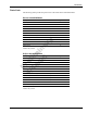
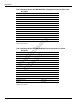
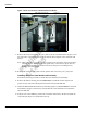


Table Of Contents

MDE-4199 Contactless Smart Card Retrofit Kit M05205K00X Installation Manual • January 2005 Page 9
Installation
Figure 2: Dual Head Card Assembly and Contactless Smart Bracket
4
Attach the contactless smart bracket and card reader to the CIM door and secure using four
Q11677-24 screws (provided in kit).
5 Reconnect the seven pin power/data cable to the 7 pin power/data connector (Figure 2) on the
card reader printed circuit card.
6 Insert the connector end of the ESD Ground Card Cable M02134A001 (Figure 3) to the two
pin connector (Figure 2) on the card reader.
Figure 3: Encore/Eclipse ESD Ground Cable M02134A001
7
Locate the ground ring terminal on the lower portion of monochrome display mounting
bracket and remove the screw and washer that secures the ground connection. Retain the screw
and washer for reinstallation.
8 Connect the ring terminal (Figure 3) of ESD Ground Card Cable M02134A001 to the
monochrome display mounting bracket ground connection. Secure the connection with the
A properly grounded electrostatic discharge wrist strap must be worn during this procedure.
Failure to use electrostatic precautions may damage electronic components and void warranty.
CAUTION
Card Reader Slot
M03311A001 Dual Head Card Assembly
Contactless Smart Bracket M01180B004
Printed
Circuit
Card
2 Pin
Antenna
Connector
7 Pin
Power/Data
Connector
2 Pin ESD
Ground
Connection
Ring Terminal
Connector