
User's Manual


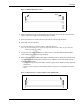
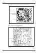
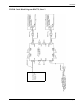
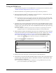
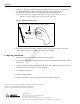
Table Of Contents
- Introduction
- Parts Lists
- Important Safety Information
- Installation
- Addressing the Gateway Board
- Installing the Enhanced Gateway Board (TRIND Electronics - M06380A001)
- Installing Light and Inductor Assembly M06143A00X
- Routing Cables
- 1 Obtain AC Power Cable M06525A001 from the kit.
- 2 Locate the M00806A00X AC Power Distribution Cable inside the electronics cabinet of the dispenser. Attach plug P1 of AC Power Cable M06525A001 to one of the AC taps on AC Power Distribution Cable M00806A00X .
- 3 Attach the ground connection of AC Power Cable M06525A001 to a convenient chassis ground.
- 4 Obtain Light/Multi-Protocol Cable R20773-G1 from the kit and connect the J182 end of the cable to P182 on Light Board Assembly M06143A001.
- 5 Secure the R20773-G1 Cable to door, and route and feed the other cables.
- 6 For both CIM Doors, use cable clamps to route cables to and along the door.
- 7 Connect the J1/J2 end of the R20773-GX cable to P2 end of the M00507A00X Ribbon Cable extending from the Card Cage Assembly .
- 8 Obtain Light/Multi-Protocol Cable R20773-G1 from the kit and connect the J182 end of the cable to P182 on the Light Board Assembly M06143A00X.
- 9 Secure the R20773-G1 Cable to the door and route the cable through the bezel.
- 10 Feed cables into the CIM door.
- 11 Use the cable clamps to route the cables to and along the door.
- 12 Connect the J1/J2 end of the R20773-G1 cable to the P1 end of the M00507A00X Ribbon Cable extending from the Card Cage Assembly.
- 13 Obtain TRIND Gateway Ribbon Cable M00515A00X from the kit and perform the following to connect Enhanced Gateway Board T20678-GX to CRIND Control Node Printed Circuit Assembly M00089A00X :
- TRIND Cable Block Diagram R20775, Sheet 2
- Enabling the TRIND Device and Verifying Addresses
- 1 Restore power to the fueling units. Refer to MDE-3804 Encore and Eclipse Series Start-Up/ Service Manual.
- 2 Initiate CRIND BIOS Diagnostics using Diagnostic Card Q12534-170.
- 3 At the Diagnostic Startup Menu window select 1. Main Menu.
- 4 At Main Menu window select 1. Device Config.
- 5 At the Device Config window select 4. TRIND.
- 6 At the TRIND Menu window for the Enable TRIND item, select 1. Yes to enable TRIND. Press ENTER on the CRIND Keypad to have the selection accepted.
- 7 Press the CANCEL key several times until the Diagnostic Startup Menu appears.
- 8 At the Diagnostic Startup Menu window select 1. Main Menu.
- 9 At the Main Menu window select 1. CRIND Config.
- 10 At the CRIND Config window select CRIND ID’s.
- 11 At the CRIND ID’s window select 1. CRIND ID Side A for side 1, or 2. CRIND ID Side B for side 2.
- 12 At the CRIND ID Side A or CRIND ID Side B window, observe and make note of the CRIND ID. Verify that the ID value is the same as the dispenser address setup on Gateway Board T20678-GX.
- Testing the TRIND Device
- 1 If the Site Controller is not operational, proceed to step 2. otherwise proceed to 6.
- 2 If the Site Controller (G-SITE® or third party) is not operational (i.e., the application has not been loaded), place the unit in the “stand alone” mode.
- 3 Locate the side 1 card cage cable harness and disconnect P1 of cable M00507A00X or locate RFID Micro Reader PCA M06100A00X tha...
- 4 Obtain Standalone Jumper Cable R20602-GX from the ASC TRIND Tool Kit, and connect the P1/P2 end of the cable to the P1 end of ...
- 5 Restore power to the card cage by reconnecting Power Cable M06525A001.
- 6 Allow about 12 seconds for the Gateway Board software to start up, then verify that the SYNC and STAT Light Emitting Diodes (LEDs) on RFID Micro Reader PCA M06100A00X flash, and the OKT LED is illuminated.
- 7 From side 1 of the unit, point the hand held test tag (Q13630-02 from the ACS TRIND tool kit) at the TRIND target graphic. The TRIND indicator will light when the tag is approximately 3 inches or less away for the target graphic. Repeat for side 2.
- 8 Once testing has been successfully completed, remove power from the unit(s), remove the jumper cable or jump jack from JP3, and restore power to the unit.
- Completing Installation
- 1 Verify that all newly installed cables and wires are properly dressed and do not obstruct CIM Door closure.
- 2 Obtain FCC label nameplate M02962B007 from the kit, and install the label near the UL and Gilbarco labels located on the inner column sheathing.
- 3 Close and secure all doors.
- 4 Install the TRIND graphics.
- 5 Clean up the work site, removing all materials to be discarded and all tools.

MDE-4544 Encore S Series TRIND Retrofit Kit C00011-011 Installation Manual • January 2006 Page 11
Installation
Draft
Figure 2: M00507A00X Ribbon Cable
J282A/J282B
P1/P2
8 Obtain Light/Multi-Protocol Cable R20773-G1 from the kit and connect the J182 end of the
cable to P182 on the Light Board Assembly M06143A00X.
9 Secure the R20773-G1 Cable to the door and route the cable through the bezel.
10 Feed cables into the CIM door.
11 Use the cable clamps to route the cables to and along the door.
Note: Be sure that cables are secured with sufficient slack to allow door to open and close
without pinching the cabling.
12 Connect the J1/J2 end of the R20773-G1 cable to the P1 end of the M00507A00X Ribbon
Cable extending from the Card Cage Assembly.
13 Obtain TRIND Gateway Ribbon Cable M00515A00X from the kit and perform the following
to connect Enhanced Gateway Board T20678-GX to CRIND Control Node Printed Circuit
Assembly M00089A00X :
• Connect J250 on gateway cable M00515A00X to plug P250 on Enhanced Gateway Board
T20678-GX
• Connect J3110 on gateway cable M00515A00X to plug P3110 on CRIND Control Node
PCA.
Figure 3: TRIND Gateway 14 Position Ribbon Cable M00515A00X
J3110
J250