
Installation Instructions


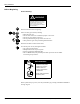
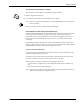


Table Of Contents
- Introduction
- Parts Lists
- Safety Information
- Installation
- Preparing for Installation
- 1 Before proceeding read and follow all safety instructions and procedures.
- 2 Open main access doors. Refer to MDE-2531, Pump and Dispenser Start-Up/Service Manual for acces...
- 3 Disconnect and remove existing hardware according to the following:
- 4 Remove door mounting pin and right options door.
- 5 If unit has Cash Acceptor, remove door alarm and all hardware from old door and save.
- 6 Dispose of door. Save pin for reassembly.
- Modifying Right Options Door On Wide Frame Units
- 1 Remove all hardware from new right options door according to the following steps and save all p...
- 2 Use center punch and hammer to mark placement of pump stop or call button hole on new right opt...
- 3 Away from fuel island, drill a 7/8 inch diameter hole in location illustrated above.
- 4 Remove any burrs around hole with deburring tool or rounded file.
- Re-installing Button
- 1 Hold contact base on back of door and align with hole drilled earlier.
- 2 Insert push button from front of door by aligning tabs with slots in base.
- 3 Turn push button 45˚ clockwise to lock button to base.
- 4 Tighten two screws on base to secure push button and base assembly to door.
- 5 Attach contact block to base with center screw if not already installed.
- 6 If unit does not have door alarm, reinstall all new right options door hardware except sheet me...
- Re-installing Door Alarm Switches
- 1 Remove lock hardware from new right options door.
- 1 Re-install C-clips removed from old right side option doors on new door.
- 2 Install door alarm assembly to door alarm assembly bracket with screw previously removed.
- 3 Attach door alarm assembly bracket to display board with screw previously removed.
- 4 Be sure magnet does not touch door alarm door bracket. Slightly move door alarm door bracket aw...
- 5 Reinstall all new right options door TRIND hardware except sheet metal cover by reversing proce...
- Installing Cables
- Position kit cables according to the following steps:
- 1 Carefully pry out printer cable retainer from underside of printer shelf.
- 2 Disconnect printer cable and pull cable out of 2 3/4" round hole from bottom, and install piece...
- 3 Feed three-prong end of power cable R20580-G2, J250 end of R20437-G01 ribbon cable and multiple...
- 4 Reinstall printer cable and retainer disconnected and removed in step 2.
- Position kit cables according to the following steps:
- Installing Card Cage
- Prepare T20538-G1 card cage for installation.
- 1 Locate tab at left front top of card cage.
- 2 From B side of unit, turning card cage sideways to unit, feed top and rear of card cage up and ...
- 3 Position card cage so that tab fits over latch cutout for main door latch to secure card cage t...
- 4 Position rear of card cage on edge of cabinet shelf for easy cable connection.
- 5 Connect three prong female end of power cable R20580-G2 to card cage at location shown.
- 6 Connect P7 on R20665-G1 to J7 and P8 on R20665-G2 to J8 on DCB at location shown.
- 7 Connect J186 on R20724-G1 cable to P186 on Gateway Board on top of card cage.
- Address Gateway Board Before Installing Card Cage
- MOC and Generic CRIND Addresses.
- Install card cage assembly.
- Prepare T20538-G1 card cage for installation.
- Installing Right Option Door
- Mount New Right Options Door
- Route cables to Right Option Doors
- 1 Route A side cable R20665-G1 through cable clamp inside door and secure along door with clamps ...
- 2 Route B side cable through clamps above CRIND tray to cable clamp inside door, and secure along...
- 3 Route cables around board as shown for both wide and narrow frame units, securing cable to boar...
- 4 Connect J182 on each cable to P182 on PCB assembly on option door.
- 5 Reinstall sheet metal cover on door, being careful to avoid crimping cables.
- Connecting Remaining Cables
- 1 From A side, pass J250 end of cable R20437-G01, J176 and JA ends of cable R20665-G1 and J177 an...
- 2 From B side, connect J176 on cable R20665-G1 to P176 on Power Supply PCB.
- 3 Connect J177 on cable R20665-G2 to P177.
- 4 Connect JA on R20665-G1 to PA on R20724-G1 cable.
- 5 Connect PA on R20665-G2 cable to JA on R20724-G1 cable.
- 6 Connect J250 on ribbon cable R20437-G01 to P250 on Gateway board on top of card cage.
- From A side of unit make the following connections:
- Connect R20580-G2 power cable according to the following:
- Preparing for Installation
- CRIND® BIOS TRIND™ Multi 1 Upgrade
- Dispenser Set-Up
- Addressing Dispenser
- Setting Baud Rate
- Testing TRIND™ Multi 1
- 1 If printer was removed, replace printer and reconnect two cables and ground.
- 2 Restore power to unit. Refer to Pump and Dispenser Service Manual MDE-2531.
- 3 Restoring power with new Bios will Cold Start the CRIND. Refer to CRIND Service Manual MDE-2562.
- 4 Present test tag at option door from a distance of 6'' or less. Light board should light and fl...
- 5 When using test tag, screen will show “Test Confirmed”. In regular operation, screen will displ...
- Completing Installation
- 1 Close and secure option and maindoor.
- 2 Install graphics. Refer to MDE-2620 Graphics Installation for The Advantage Series.
- 3 Peel backing paper off FCC label pate provided in kit.
- 4 Affix FCC label plate to inside frame sheathing on column under existing FCC label.
- 5 Restore power to unit. Refer to Pump and Dispenser Service Manual MDE-2531.
- Cable Block Diagrams

Parts Lists
Page 4 MDE-3801 TRIND™ Multi 1 Transmitter/Receiver in Dispenser Retrofit Kit • 10/99
Kits for Narrow Frame Units, Dual- and Single-Sided
Kits C00012-001-NF-D (dual-sided) and C00012-001-NF-S (single-sided) for The
Advantage Narrow Frames (36’’) contain the following parts.
Note: Right Option Door Graphics T50149-G1 are an Order Entry Item.
Description Part Number Quantity WF-D Kit Quantity NF-S Kit
cable clamp, gray Q13558-04 12 12
cable group Q13781-01 For components see table “Q13781-01
Cable Group” on page 3.
cable tie Q10178-02 8 8
card cage assembly T20538-G1 1 1
door assembly, right options clear with TRIND T20539-G1 2 1
graphics, right option door T50148-G1 (see note) (see note)
grommet strip, solid Q10315-06 .583 ft. .583 ft.
jump jack Q11011-01 10 10
label plate, FCC N23936-01 1 1
manual, graphics installation instructions MDE-2620 1 1
manual, installation instructions MDE-3801 1 1
nut Q12068-04 2 2
software (firmware) CRIND
®
BIOS
K93744-01 2 1