MDE-4017A Mat Reader Assembly Kit C00016-XXX Installation September 2001 Introduction Purpose of this Manual a 01 r y This manual provides instruction for installing Mat Reader Assembly Kit C00016-XXX. The Mat Reader allows customers to automatically authorize sales using a hand-held transponder tag.
Important Safety Information Important Safety Information Preliminary Precautions i 3/ na 01 r y This section introduces the hazards and safety precautions associated with installing, inspecting, maintaining or servicing this product. Before performing any task on this product, read this safety information and the applicable sections in this manual, where additional hazards and safety precautions for your task will be found.
Important Safety Information Safety Symbols and Warning Words Alert Symbol Signal Words i 3/ na 01 r y This safety alert symbol is used in this manual and on warning labels to alert you to a precaution which must be followed to prevent potential personal safety hazards. Obey safety directives that follow this symbol to avoid possible injury or death. These signal words used in this manual and on warning labels tell you the seriousness of particular safety hazards.
Reference Information Reference Information Related Documents i 3/ na 01 r y Installer must obtain, read and understand all site preparation documentation provided by the point of sale company authorizing the installation before attempting to install this equipment.
Parts Lists Parts Lists C00016-006 Kit - Low Frequency Description box, interface assembly tape, neoprene foam channel, plastic filler cable, mat reader drive ferrite half ferrite, snap-on tape, acrylic foam Pr e 09 lim power supply i 3/ na 01 r y C00016-006 Kits contain the following parts: jack, jump cable, data, CAT-5 clamp, cable, stick on, small decal, UL/FCC document, installation screw, thread forming, 8-32x3/8” Part Number Quantity M01814A001 1 M01870B001 2 M01871B001 1 M01872A00
Parts Lists Mat Reader The following component is also required in addition to the C00016-XXX kit. mat reader Part Number Quantity i 3/ na 01 r y Description MR01002GXXX 1 /1 Pr e 09 lim Note: XXX is the graphic-specific identifier.
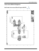
Interconnect/Block Diagrams Interconnect/Block Diagrams Page 7 115VAC DC +12VDC In Interface Box Assembly M01814A001 /1 Pr e 09 lim In Mat Reader Assembly MR01002GXXX i 3/ na 01 r y Mat Reader Interconnect/Block Diagram M01873 MDE-4017A Mat Reader Assembly Kit C00016-XXX Installation • September 2001
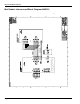
Interconnect/Block Diagrams Page 8 NOTE: FOR DAISYCHAINING, FOLLOW INSTRUCTIONS IN THE “ADDRESSING LOGIC BOARD - ONLY FOR DAISYCHAINING” SECTION OF MDE-4017.
Installation Installation i 3/ na 01 r y Note: All installation work is to be accomplished between the hours specified by the point of sale company authorizing the installation. Install the Mat Reader assembly according to the following instructions. Collect and arrange for safety and convenience all tools and equipment.
Installation In Relation to the Interface Box i 3/ na 01 r y For optimum Mat Reader performance, the Interface Box should be positioned as close to the Mat Reader as is conveniently possible. If necessary, the CAT-5 cable, Q13482-06, may be swapped out for a longer version in order to properly place the Interface Box and still reach the POS connection. The dash number, such as -06, indicates 6 feet (1.8 meters) long.
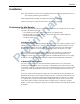
Installation Setting Baud Rate 1 Remove Mat Reader Interface Box cover to access the logic board.
Installation 2 Locate jump jacks on logic board for Mat Reader.
Installation 3 Set the jump jacks as follows (see the appropriate figure: “Figure: Jump Jacks for Baud Rate Setting - M01803A001” on page 12 or “Figure: Jump Jacks for Baud Rate Setting M01803A002” on page 12). i 3/ na 01 r y CAUTION Electrostatic Discharge Damage Working on electronics without connecting to a ground or discharging static can damage electronic parts. Use a wrist strap.
Installation Addressing Logic Board - Only for Daisychaining Address for Mat Reader must match address on previously installed Mat Reader. Follow these steps: i 3/ na 01 r y 1 Access logic board for Mat Reader being installed. 2 Locate jump jacks on previously installed Mat Reader logic board M01803A001 or M01803A002 as appropriate.
Installation 3 Note position of jump jacks on previously installed Mat Reader logic board, and set jump jacks on board for Mat Reader being installed to match address on logic board. CAUTION i 3/ na 01 r y Electrostatic Discharge Damage Working on electronics without connecting to a ground or discharging static can damage electronic parts. Use a wrist strap.
Installation Mounting Mat Reader Interface Box 1 Determine the location for the installation of indoor equipment. The Interface Box may be i 3/ na 01 r y mounted under the counter top (upside down) or vertically on one of the supporting walls of the counter top. Note: Refer to site prep document provided by point of sale company and keep in mind overall 5-foot (1.5 meter) length of cable to connect Mat Reader Interface Box to Mat Reader. Also refer to “In Relation to the Interface Box” on page 10.
Installation Connecting Data Cables to Mat Reader Interface Box Run both power and data cables to port end of Mat Reader Interface Box (see “Figure: Mat Reader Interface Box Mounting Holes” on page 16) as follows: i 3/ na 01 r y 1 Connect the P3 end of the ribbon cable (M01872A001) to the interface port (P3). 2 Connect the J1 end of the CAT-5 cable (Q13482-06) to the J1IN port.
Installation Connecting Data Cables from the Mat Reader Interface Box Low Frequency Mat Reader i 3/ na 01 r y 1 Position Mat Reader face down.
Installation Figure: Connecting to Mat Reader - Low Frequency carefully connect these neoprene foam tape neoprene foam tape 7-pin cable connector ribbon cable acrylic foam tape unused channel Pr e 09 lim channel for ribbon cable i 3/ na 01 r y plastic channel filler 6 Peel release liner and install neoprene foam tape (M01870B001) over ribbon cable and sides of channel. Foam tape should fit snugly into cutout of surrounding foam tape backer.
Installation High Frequency Mat Reader 1 Position Mat Reader face down. neoprene foam tape 7-pin cable connector ribbon cable acrylic foam tape Pr e 09 lim channel for ribbon cable i 3/ na 01 r y Figure: Bottom Side of Mat Reader - High Frequency coaxial cable plastic channel filler 7-pin Mat Reader connectors (only one used) bottom side of Mat Reader 2 Select side for ribbon cable (M01872A001) connection based on counter top configuration /1 requirements.
Installation Figure: Connecting to Mat Reader - High Frequency carefully connect these neoprene foam tape 7-pin cable connector ribbon cable acrylic foam tape coaxial cable unused channel Pr e 09 lim channel for ribbon cable i 3/ na 01 r y plastic channel filler 7 On unused cable channel, install plastic filler channel (M01871B002). 8 Install neoprene foam tape (M01870B002) over filler channel, ribbon cable, and coaxial cable.
Installation Connecting Power Supply Connect the power supply (M01878B001) provided with kit as shown. 1 Plug the wall-mounted transformer into the AC power outlet. i 3/ na 01 r y Note: If the POS is a G-SITE system, this AC power outlet must be on the same circuit as the G-SITE system.
Installation Completing the Installation Low Frequency Mat Reader i 3/ na 01 r y Figure: Low Frequency Mat Reader Connections power supply Q11433-107 ferrite steel clips /1 Pr e 09 lim Mat Reader interface box ribbon cable CAT-5 cable connects here Q11433-110 ferrite halves 1 Install both ferrite halves Q11433-110 on ribbon cable, and secure with steep clips, as shown.
Installation 4 Install M01868A001 UL/FCC decal, as appropriate, as shown in “Figure: Mat Reader Interface Box Mounting Holes” on page 16. 5 Clean up the work area. i 3/ na 01 r y 6 Verify the keytag can be read by the mat reader within the specified range. Pr e 09 lim Figure: Low Frequency Mat Reader Read Verification 2.0-4.0 inches (5-10 cm) /1 7 Go to “Commissioning and Warranty Information” on page 27.
Installation High Frequency Mat Reader Figure: High Frequency Mat Reader Connections Pr e 09 lim mat reader /1 Q11433-107 ferrite CAT-5 cable connects here interface box i 3/ na 01 r y power supply steel clips Q11433-106 ferrite Coaxial cable ribbon cable Q11433-110 ferrite halves 1 Install both ferrite halves Q11433-110 on ribbon cable, and secure with steep clips, as shown.
Installation 3 Install clip-on ferrite (Q11433-106) in pass-through configuration on coaxial cable at Interface Box connection. Q11433-106 ferrite i 3/ na 01 r y Coaxial cable SMA connector 4 Dress all cables and secure with stick on cable clamps (Q13459-01). 5 Install M01868A002 UL/FCC decal, as appropriate, as shown in “Figure: Mat Reader Interface Box Mounting Holes” on page 16. 6 Clean up the work area. Pr e 09 lim 7 Verify the keytag can be read by the mat reader within the specified range.
Commissioning and Warranty Information Commissioning and Warranty Information i 3/ na 01 r y Upon completion and testing the Mat Reader system, the installing contractor must call the Marconi Commerce Systems Call Center at 1-888-800-7498 to register the installation and activate the warranty. Note the installed unit’s full Model Number (C00016-XXX) and serial number before making this call. • All Mat Readers have a one-year parts only warranty.
/1 Pr e 09 lim i 3/ na 01 r y Commissioning and Warranty Information G-SITE® and Gilbarco® are regsitered trademarks of Marconi Commerce Systems Inc. GOLDSM is a service mark of Marconi Commerce Systems Inc. Corian® is a registered trademark of E.I. Du Pont De Nemours and Company. Formica® is a registered trademark of Formica Corporation. Phillips® is a registered trademark of Phillips Screw Company. UL® is a registered trademark of Underwriters’ Laboratories, Inc.