
User Manual


Br-ANA Panel Indicators
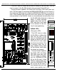
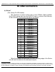
There are forty-six LED indicators on the front of the Br-ANA. They are used as fol-
lows:
A) Output Fuse Indicators
(Four Green LEDs)
These four LEDs are lit unless one of the four PTC fuses has been
tripped by an overload on the J6/A output cable.
B) Output Level Indicators
(Sixteen Red LEDs)
! These sixteen red LEDs show the output level on all sixteen of the 0-
10 volt outputs. You will see these LEDs fade in and out as the signals on
the outputs change.
! Very low levels may not be indicated accurately on the LEDs:
a) If the negative reference is tied to ground, the LEDs will not
begin to glow until the output gets above about 1.75 volts.
b) If the negative reference is not grounded, there may be a
slight glow even when the outputs are sending out a zero
voltage signal. There can also be a slight crosstalk in the
LEDs as their neighbors brighten and dim. This is only on the
indicators. The actual outputs do not cross talk.
C) J8 Input LEDs
(Four Green LEDs)
These LEDs indicate the status of the four optically isolated trigger inputs
on the Br-ANA. They are on the isolated side of the optoisolators. If they are
not on when you send a trigger to the Br-ANA, then there is an external wir-
ing problem, the ʻinternal/externalʼ power switch needs to be changed for
your wiring setup, or the optoisolator has been damaged.
D) Busy LED
(One Red LED)
Gilderfluke & Co.• 205 South Flower Street • Burbank, California 91502 • 818/840-9484 • 800/776-5972 • fax 818/840-9485
Br-ANA Manual / December 18, 2012 10:21 AM / page 11 of 60