
User Manual
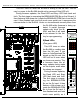
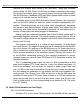


output wire #
J6/A pin #
Edge pin #
color
wire function
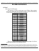
J6/A #31
31
41
brown
circuit ground
J6/A #32
32
42
red
+ power output (protected to 1 amp)
J6/A #33
33
43
orange
Output 3 (03h) Positive Analog Output
J6/A #34
34
44
yellow
Output 3 (03h) Negative Reference
J6/A #35
35
45
green
Output 2 (02h) Positive Analog Output
J6/A #36
36
46
blue
Output 2 (02h) Negative Reference
J6/A #37
37
47
violet
Output 1 (01h) Positive Analog Output
J6/A #38
38
48
gray
Output 1 (01h) Negative Reference
J6/A #39
39
49
white
Output 0 (00h) Positive Analog Output
J6/A #40
40
50
black
Output 0 (00h) Negative Reference
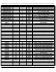
51
black
power supply ground
52
black
power supply ground
53
black
power supply ground
54
black
power supply ground
55
black
power supply ground
56
red
+ power supply input
57
red
+ power supply input
58
red
+ power supply input
59
red
+ power supply input
60
red
+ power supply input
The card cages from Gilderfluke & Company are available in a variety of
sizes to hold between one to sixteen cards. Some of these card cages are
designed to be mounted in standard 19” electronics racks. Others are de-
signed to be mounted standalone, on DIN rail or in Augat SnapTrak. The
smaller card cages bring out the center forty connections of the sixty position
backplane connector to either a forty position screw terminal block, a forty
position ribbon cable connector, or both. The Br-CC16 (sixteen slot) and Br-
CC09 (two slot) rack mounted card cages have only ribbon cable connectors
on them, but we have cc-BR16BO spring blocks that can mount directly to
the back of these card cages for attaching discrete wires. More commonly
the ribbon cables are run to a rail at the back of the rack or a nearby ʻbreak
out boxʼ, and c-40trans ribbon cable-to-screw terminal connectors are
mounted there allow discrete wires to be attached.
In all the animation systems made by Gilderfluke & Company, all Analog
input and output cabling is through what we call 'J6/A' standard output rib-
bon cables
4
. These are forty wire ribbon cables which are made up of four
Gilderfluke & Co.• 205 South Flower Street • Burbank, California 91502 • 818/840-9484 • 800/776-5972 • fax 818/840-9485
Br-ANA Manual / December 18, 2012 10:21 AM / page 18 of 60
4
Please note that the pinout of a J6 Digital output cable and a J6/A Analog output cable is completely different. Do not cross con-
nect any analog and digital cables. Damage can (and probably will) result.