
User Manual


identical four channel wide cables of ten wire each. These split individual
cables called 1/4 J6/A. Each 1/4 J6/A also includes a common power supply
and ground wire which allow it to provide power for analog output accesso-
ries like Electronic FeedBack (EFB) controllers (these cards require a power
supply of 18 volts be used for the Br-ANA).
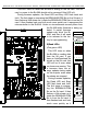
To simplify wiring to any MACs Animation Control System, the connectors
used on the J6/A cables are what are called 'insulation displacement con-
nectors'. These simply snap on to an entire cable, automatically 'displacing'
the insulation and making contact with the wires within. This means that an
entire forty wire cable can be terminated in seconds. All connectors are po-
larized, to keep them from being plugged in backwards.
Analog loads are connected between each of the Positive outputs and its
associated Negative reference. The output capacity of each output is 50 ma.
The output voltage range can be adjusted from the Br-ANA to anywhere be-
tween 0 and 10 volts.
The negative reference is at a voltage of approximately 1.6 volts above
the circuit ground. The negative references are all connected on the Br-ANA,
but not to ground. On versions of the BS-ANA prior to 3.0, there could be no
direct connections made between any of the negative references and the
circuit grounds anywhere in the animation system. Starting with version 3.0
of the Br-ANA, connecting ground to the negative references is recom-
mended unless you have an older EFB-Quad or PID-Quad that requires the
negative reference.
The '+ unregulated power output' for each 1/4 J6/A is protected by a solid
state circuit breaker (PTC Fuse) rated for 1 amp. You should treat each 1/4
J6/A as an individual, and not cross the outputs or power output lines from
one 1/4 J6/A to the lines from another. Doing this won't cause any damage,
but can reduce the protection for the outputs that the circuit breakers nor-
mally provide. The 'Output Fuse' LEDs on the front of the Br-ANA show the
condition of each of the PTC fuses. Each of these is a LED and resistor be-
tween the ground (pin #1 brown) wire and power output (pin #2 red) wire.
Each of these will be lit if the corresponding circuit breaker is OK. The resis-
tor is 4.7 Kohms.
D) ʻSmartʼ Brick Network (on Card Cage)
(RJ-12 or RJ-45 Connector)
If Switch #4 is in the ʻSmartʼ Brick position, the Br-ANA will be operating
Gilderfluke & Co.• 205 South Flower Street • Burbank, California 91502 • 818/840-9484 • 800/776-5972 • fax 818/840-9485
Br-ANA Manual / December 18, 2012 10:21 AM / page 19 of 60