
User guide
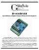


Br-miniBrick8 LEDs, Switches and Connections
There are only a small number of connections on each Br-miniBrick8. You will
need to attach a power supply, whatever you are controlling, and (optionally) a switch
(or two) to start the Br-miniBrick8:
LEDs:
1. Eight red LEDs show the status of the eight outputs. They also flash in a fast, very
bright ʻdouble flashʼ to indicate that an individual channel is enabled for programming
using the buttons on the Br-miniBrick8. These eight LEDs flash in a back-and-forth
chase to indicate that the Br-miniBrick8 is in the ʻclear allʼ mode, and that the but-
tons will be used to clear the memory of the Br-miniBrick8. During serial down-
loads, these eight LEDs will chase in a sequential pattern.
2. Two green LEDs show the status of the two optically isolated inputs. These LEDs
are located on the ʻ insideʼ of the optical isolators. They will operate if the input is re-
ceiving a signal, and it is getting to the Br-miniBrick8ʼs microprocessor. While set-
ting the ʻoperating modeʼ for the Br-miniBrick8 using the buttons on its front, these
LEDs will flash in the same quick double-flash pattern as the red ʻoutputʼ LEDs.
When receiving DMX-512 or serial RealTime data, the Br-miniBrick8 no longer
needs the two trigger inputs or their indicator LEDs:
a. The ʻAʼ inputʼs LED is borrowed to toggle on each frame received. If receiving
DMX-512 data at 30 FPS, the LED will be flashing at 15 Hz.
b. The ʻBʼ inputʼs LED is borrowed to flash each time there is an error in the re-
ceived DMX-512 or Serial RealTime data. If you see this flashing any more
than occasionally, check your DMX-512 wiring. You may need to terminate
the DMX-512 data lines with a 120Ω resistor.
3. One LED is attached to the serial data transmission line on the Br-miniBrick8. The
Tx LED is used as a ʻheartbeatʼ so that you can see that the Br-miniBrick8 is alive.
If the RS-232 serial port is attached to a PC, then the flash will be very short and
quick, as the Br-miniBrick8 sends out a ʻfʼ to mark a frame, or a ʻ.ʼ if it is not cur-
rently running a show. When the RS-232 cable is disconnected, then this LED will
flash with a 50%/50% duty cycle. If this LED doesnʼt flash at least once per second,
you should power down the Br-miniBrick8 and check the power supply and connec-
tions to the Br-miniBrick8.
4. One LED is attached to the serial data received line on the Br-miniBrick8. If the RS-
232 serial port is attached to a PC, you will see this LED flash each time a data is
received through the serial port. If the RS-232 serial cable is disconnected, then the
LED will flash at a high rate of speed as DMX-512 data is being received.
Red ʻRecordʼ button:
The red ʻrecordʼ button is used for programming the Br-miniBrick8 without a com-
puter. See the ʻProgramming without a Computerʼ section of the manual for details on
the use of this button. The red ʻRecordʼ button electronically locks the Br-miniBrick8ʼs
nonvolatile EEprom memory whenever it is released. Nothing in the programming can
change unless this button is being held down. With the memory write protected, it
should retain whatever has been programmed into the Br-miniBrick8 for at least forty
years.
Gilderfluke & Co.• 205 South Flower Street • Burbank, California 91502 • 818/840-9484 • 800/776-5972 • fax 818/840-9485
Br-miniBrick8 v3.+ Manual / 8/17/12 / page 4 of 36