
User Manual


Any event can be triggered on either the ʻclosingʼ or ʻopeningʼ edge of any input. A
ʻclosingʼ is when you ground an input. An ʻopeningʼ is when that grounding is removed.
The inputs can be triggered on any voltage from 9 to 24 VDC. If you donʼt have an ex-
ternal source of power for these two inputs, you can ʻstealʼ some juice from the Br-
SDCʼs power supply.
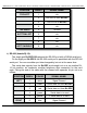
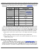
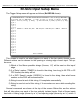
ʻ8ʼ & ʻ9ʼ Inputs:
These are two optically isolated digital inputs. Unlike the 1/4-J6 inputs, these can be
wired to switch either side of the photo diode:
External Power
(+ 5-24 VDC supply)
terminal #1
terminal #2
terminal #3
terminal #4
DATA BIT 8
DATA BIT 9
Versions of the Br-SDC 2.0 or later use a bipolar optoisolator on inputs 8 and 9. This
means that you can ignore the polarity markings shown in the above illustrations on all
versions of the Br-SDC 2.0 and later.
Any event can be triggered on either the ʻclosingʼ or ʻopeningʼ edge of either input. A
ʻclosingʼ is when you apply a voltage to an input. An ʻopeningʼ is when that voltage is
removed. The inputs can be triggered on any voltage from 5 to 24 VDC. If you donʼt
have an external source of power for these two inputs, you can ʻstealʼ some juice from
the Br-SDCʼs power supply.
Power Supply:
(5.5 mm O.D. / 2.1 mm I.D. power jack)
The Br-SDC can be run from any supply voltage from 9-24 VDC.
The outer ring is used for the ground, and the middle pin is used for the positive con-
nection. This input is protected from reverse polarity connections. An idle Br-SDC draws
only about twenty-five milliamperes. It can run for days on just a single nine volt battery.
Gilderfluke & Co.• 205 South Flower Street • Burbank, California 91502 • 818/840-9484 • 800/776-5972 • fax 818/840-9485
Br-SDC Manual / December 30, 2013 9:24 AM / page 13 of 62