
User Manual


data out and Rx data in pins on your USB-to-Serial converter. For an RS-232 port, this
means temporarily shorting pins #2 and #3 together. On the C-USB-RS232, the pinout
is as follows:
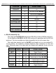
POSITION
WIRE #
SIGNAL NAME:
TOP-LEFT
TOP-RIGHT
BOTTOM-LEFT
BOTTOM-RIGHT
1
n/c
2
RS-232 Rx to C-USB-RS232
3
RS-232 Tx from C-USB-RS232
4
n/c
5
Ground
6
n/c
7
n/c
8
n/c
9
n/c
While still running the modem program, anything you type should be shown on the
screen while these jumpers are in place, while nothing will appear when you remove
them. If your computer passes this test, then you are using the right serial port and the
problem is most likely the baud rate setting or in your wiring to the Br-SDC. If you get
characters on the screen even with the jumpers removed from the serial port, it means:
a) You need to set the 'echo' mode to 'none' or 'full duplex' and try this test again,
or…
b) You are talking to a different serial port than the one you actually want.
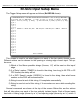
3) String Setup: This screen is used to set up which characters are sent and re-
ceived in each string.
Entering Configuration Mode:
To enter the configuration mode you need to move the ʻConfigure/Runʼ Switch to the
ʻconfigureʼ position. The ʻheartʼ LED will begin flashing at about four times per second,
instead of the usual twice per second. The Br-SDC will then send out its menu through
the main serial port. If you have a computer attached and running a terminal program
Gilderfluke & Co.• 205 South Flower Street • Burbank, California 91502 • 818/840-9484 • 800/776-5972 • fax 818/840-9485
Br-SDC Manual / December 30, 2013 9:24 AM / page 16 of 62