
User guide


400
600
500
300
200
100
0
2
3
4
5
8
7
6
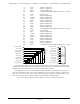
NUMBER OF OUTPUTS
CONDUCTING
SIMULTANEOUSLY
PER CENT DUTY CYCLE
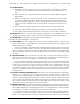
ALLOWABLE PEAK COLLECTOR CURRENT IN mA AT 70ºC
PEAK COLLECTOR CURRENT
AS A FUNCTION OF DUTY CYCLE
10 20 30 40 50 60 70 80 90 100
Since it is unusual to have more than 50% of the outputs on at any one time, you can
usually assume the system has a 250 ma output current capacity. If you are going to be turn-
ing on lots of heavy loads at the same time, you should derate this to 150 ma.. This is suffi-
cient to drive the majority of loads that will be directly connected to the outputs of the anima-
tion system. FSK/RTUs use a Micrel MIC58P01CN output driver chip. These chips add output
protection to each individual output which acts much like an electronic circuit breaker. When
the rated output of a chip is exceeded, it will turn ‘OFF’. To reset the output, just temporarily
power down the FSK/RTU.
If additional current capacity is needed, or if you need to drive higher voltage loads, you
can connect relays as needed to the outputs of the animation system. Coincidentally, boards
for doing this are available from Gilderfluke & Company. These include:
Solid State Output Drivers: These snap track mounted cards each have eight optoiso-
lated outputs. Current capacities available range from 700 ma. up to 3.5 amps. The
lower current models are internally protected.
DPDT relay board: A set of eight electromechanical relays with double pole/double
throw contacts rated at 5 amps each.
Reed relay board: A set of eight small electromechanical relays with normally open
contacts rated at 150 ma each.
I/O module: A set of eight small solid state relays with normally open contacts rated at
3.5 amps each (AC and DC relays available).
Solid State Relay Fanning Strip: For connecting up to eight popular ‘hockey puck’
style relays to a 1/4 J-6 output cable. These are available with capacities of up to 75
amps each.
F) One J6/A Analog Data Output (optional) : In all the animation systems made by Gilderfluke &
Company, all Analog input and output cabling is through what we call ‘J6/A’ standard output
cables. These are 40 wire cables which are made up of four identical four channel wide ca-
bles. A J6/A cable is often split up into four individual cables called a 1/4 J6/A. Each 1/4 J6/A
also includes a common power supply and ground wire which allow it to provide power for
analog output accessories like Electronic FeedBack (EFB) controllers and 16 Channel Servo
Controllers.
To simplify wiring to any MACs animation system, the connectors used on the J6/A cables
GILDERFLUKE & CO. • 205 SOUTH FLOWER ST. • BURBANK, CALIF. 91502-2102 • 818/840-9484 • FAX818/840-9485
5 of 25