
Manual


to glow as the valve opens and the actuator starts to follow the position commands . Continue
turning the gain up until the movement starts to show signs of oscillation.
3) Turn velocity control clockwise to stop the oscillation. Now turn it back down (counter-clockwise)
until you find the point just above where the movement can be made oscillate by applying fast
moving command voltages.
At this point the movement should be adjusted reasonably well. Depending on the nature of the
movement, you may want to continue to tweak it to taste.
The low gain control is usually set at it's minimum value (fully counter-clockwise). If you want to adjust
it, you will need to force an error condition by temporarily unplugging the wire for that circuit. It will stay
in error condition for about 10 seconds, during which time you can adjust it.
Quad D/A and EFB (ÒGeorge BoardÓ):
This board combines the functions of a Quad D/A converter and a Quad EFB. The adjustments are a
combination of those you would find on both of these other products. The only function which was
eliminated is the Ôlow gainÕ control on the EFB. When a transducer wire break occurs, the gain will
immediately go to its lowest possible value, effectively shutting off the valve. The valve and transducer
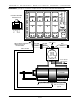
connections, indicator LEDs, and adjustments are arranged as follows.
00h level
ffh level
velocity
gain
level
wire break
valve
valve
board error
00h level
ffh level
velocity
gain
level
wire break
valve
valve
00h level
ffh level
velocity
gain
level
wire break
valve
valve
00h level
ffh level
velocity
gain
level
wire break
valve
valve
CHANNEL 0
CHANNEL 1
CHANNEL 2
CHANNEL 3
yellow
green
red
black
valve
feedback
As with the regular Quad EFB controller, the wire break error signal from all four channels is summed
to a single indicator LED and output. This is a optoisolated transistor output on pins 4 (collector) and 6
(emitter) of the backplane connector. This output can drive a LED, solid state relay, or small
electromechanical relay. There is also a four pin jumper header, which when two jumpers are installed
horizontally will bring these same signals out to pins 1(collector) and 6 (emitter) on the backplane. These
connect to the white and blue wires on the backplaneÕs RJ-11, which are unused if the rest of the cage
is populated with other Quad D/A&EFB boards or dumb bricks, but which is incompatible with any smart
bricks in the cage. These jumpers are normally left off.
Note: The Wire Break Collector & Emitter are the 2 wires used by the George Board to transmit
remote wire break indication. If you do not need this feature you can isolate the George board from the
back plane by removing the 2 jumpers located near edge pin #1.
Caution : Never connect edge pins 1& 2 of a George Board to edge pins 1 & 2 of a brick card
unless the 2 jumpers near edge pin 1 are removed.
GILDERFLUKE & CO. ¥ 205 SOUTH FLOWER ST. ¥ BURBANK, CALIF. 91502-2102 ¥ 818/840-9484 ¥ FAX818/840-9485
4 of 5