
User Manual


¥¥¥¥¥¥¥¥¥¥¥¥¥¥¥¥¥¥¥¥¥¥¥¥¥¥¥¥¥¥¥¥¥¥¥¥¥¥¥¥¥¥¥¥¥¥¥¥¥¥¥¥¥¥¥¥¥¥¥¥¥¥¥¥¥¥¥¥¥¥¥¥¥¥¥¥¥¥¥¥¥¥¥¥¥¥¥¥¥¥¥¥¥¥¥¥¥¥¥¥¥¥¥¥¥¥¥¥¥¥¥¥¥¥¥¥¥¥¥
5) J-8 input: This input has two optically isolated inputs on it which can be used for starting, stop-
ping, stepping, resetting, or a variety of other functions in the system.The exact function of
these inputs is set when you configure the Smart Brick Brain. This input has the same pinout
and polarity as the J-8 connections found on all of our normal Micro MACs Bricks. Facing the
end of the plug with the latch upward, the order of these inputs is as follows:
COLOR SIGNAL NAME:
1) WHITE: not used
2) BLACK: common + 5 to 24 VDC (15 Volts nominal) input
3) RED: not used
4) GREEN: optically isolated input
5) YELLOW: not used
6) BLUE: optically isolated input
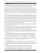
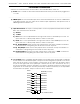
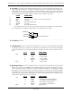
The Connections to the J-8 input are as follows. As these are feeding into an optoisolator,
you must provide a voltage to the Brick Brain on the BLACK input line (#2):
+
GREEN #4
BLUE #6
BLACK #2
+ 5 to 24 VDC SUPPLY
¥¥¥¥¥¥¥¥¥¥¥¥¥¥¥¥¥¥¥¥¥¥¥¥¥¥¥¥¥¥¥¥¥¥¥¥¥¥¥¥¥¥¥¥¥¥¥¥¥¥¥¥¥¥¥¥¥¥¥¥¥¥¥¥¥¥¥¥¥¥¥¥¥¥¥¥¥¥¥¥¥¥¥¥¥¥¥¥¥¥¥¥¥¥¥¥¥¥¥¥¥¥¥¥¥¥¥¥¥¥¥¥¥¥¥¥¥¥¥
6) J-8 output: Not used
¥¥¥¥¥¥¥¥¥¥¥¥¥¥¥¥¥¥¥¥¥¥¥¥¥¥¥¥¥¥¥¥¥¥¥¥¥¥¥¥¥¥¥¥¥¥¥¥¥¥¥¥¥¥¥¥¥¥¥¥¥¥¥¥¥¥¥¥¥¥¥¥¥¥¥¥¥¥¥¥¥¥¥¥¥¥¥¥¥¥¥¥¥¥¥¥¥¥¥¥¥¥¥¥¥¥¥¥¥¥¥¥¥¥¥¥¥¥¥
7) To Smart Bricks: This is the start of the cable which runs to all of the Smart Bricks and Heads
Up Displays installed in the system. All signals are compatible with RS-422 and RS-485 signal
levels. Facing the end of the plug with the latch upward, the order of these outputs is as fol-
lows:
pin # COLOR SIGNAL NAME:
(left) 1 WHITE + data output
2 BLACK - data output
3 RED + clock output
4 GREEN - clock output
5 YELLOW + strobe output
(right) 6 BLUE - strobe output
¥¥¥¥¥¥¥¥¥¥¥¥¥¥¥¥¥¥¥¥¥¥¥¥¥¥¥¥¥¥¥¥¥¥¥¥¥¥¥¥¥¥¥¥¥¥¥¥¥¥¥¥¥¥¥¥¥¥¥¥¥¥¥¥¥¥¥¥¥¥¥¥¥¥¥¥¥¥¥¥¥¥¥¥¥¥¥¥¥¥¥¥¥¥¥¥¥¥¥¥¥¥¥¥¥¥¥¥¥¥¥¥¥¥¥¥¥¥¥
8) RS-422 Serial Port: This is the serial port which is used to send commands to the Smart Brick
System or to connect a LaserDisk to the Smart Brick System. It must be connected to a termi-
nal or computer running a modem or terminal emulation program for configuring the Smart
Brick System. This is the same style of connector and pin out as is used on the AB-100 Digital
Audio Repeaters, and can be attached to both Brick Brains and Digital Audio Repeaters simul-
taneously, just so long as their addresses donÕt conflict. Facing the end of the cable with the
release latch upwards, its pin out is as follows:
pin # COLOR SIGNAL NAME:
(left) 1 WHITE signal ground
2 BLACK - serial data out from Brick Brains
3 RED + serial data out from Brick Brains
4 GREEN - serial data in to Brick Brains
5 YELLOW + serial data in to Brick Brains
(right) 6 BLUE signal ground
GILDERFLUKE & C
O
.¥ 205 S. FLOWER ST.¥ BURBANK, CA 91502 ¥ 818/840-9484 ¥ 800/776-5972 ¥ FAX 818/840-9485
10 of 134