
Manual

Quad D/A and EFB (“George Board”):
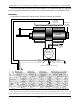
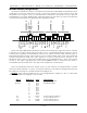
This board combines the functions of a Quad D/A converter and a Quad EFB. The adjustments are a
combination of those you would find on both of these other products. The only function which was
eliminated is the ‘low gain’ control on the EFB. When a transducer wire break occurs, the gain will
immediately go to its lowest possible value, effectively shutting off the valve. The valve and transducer
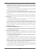
connections, indicator LEDs, and adjustments are arranged as follows.
00h level
ffh level
velocity
gain
level
wire break
valve
valve
board error
00h level
ffh level
velocity
gain
level
wire break
valve
valve
00h level
ffh level
velocity
gain
level
wire break
valve
valve
00h level
ffh level
velocity
gain
level
wire break
valve
valve
CHANNEL 0
CHANNEL 1
CHANNEL 2
CHANNEL 3
yellow
green
red
black
valve
feedback
As with the regular EFB-Quad or PID-Quad controller, the wire break error signal from all four channels
is summed to a single indicator LED and output. This is a optoisolated transistor output on pins 4
(collector) and 6 (emitter) of the backplane connector. This output can drive a LED, solid state relay, or
small electromechanical relay. There is also a four pin jumper header, which when two jumpers are
installed horizontally will bring these same signals out to pins 1(collector) and 6 (emitter) on the
backplane. These connect to the white and blue wires on the backplane’s RJ-11, which are unused if
the rest of the cage is populated with other Quad D/A&EFB boards or dumb bricks, but which is
incompatible with any smart bricks in the cage. These jumpers are normally left off.
Note: The Wire Break Collector & Emitter are the 2 wires used by the George Board to transmit
remote wire break indication. If you do not need this feature you can isolate the George board from the
back plane by removing the 2 jumpers located near edge pin #1.
Caution : Never connect edge pins 1& 2 of a George Board to edge pins 1 & 2 of a brick card
unless the 2 jumpers near edge pin 1 are removed.
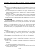
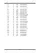
wire # Edge pin # color wire function
J8 Black 1 N/A Wire Break Collector
J8 White 2 N/A Wire Break Emitter
3 N/A
4 N/A
5 N/A
6 N/A
7 N/A
8 N/A
9 N/A
10 N/A
#1 11 brown J6 out channel 0 Ground
#2 12 red J6 out channel 0 bit 7
#3 13 orange J6 out channel 0 bit 6
#4 14 yellow J6 out channel 0 bit 5
GILDERFLUKE & CO. • 205 SOUTH FLOWER ST. • BURBANK, CALIF. 91502-2102 • 818/840-9484 • FAX818/840-9485
11 of 12