
Manual

The PID-Quad also features what are called ‘Compliance’ inputs. This adds a second
‘force’ feedback to an analog movement. This is usually a strain gauge or accelerometer
mounted on the cylinder in addition to the normal position sensor. This measures the force
being applied by the cylinder and feeds this to the FeedBack card. Sometimes an
accelerometer on the movement or differential pressure transducer on the valve are used
for a lower cost.
As a compliant movement is commanded to accelerate quickly, the inertia of the
mass of the movement applies a force to the strain gauge. This gets amplified and
added to the signal that the PID-Quad sends to the valve to open it further than just the
positional error would have made it open. Conversely, when the movement is
commanded to decelerate quickly, the strain gauge picks up the mass of the movement
in the opposite direction and the feedback card can open the valve in the reverse
direction to apply active braking to the movement as it approaches its target position.
The other thing that compliance does to a figure is to ‘soften’ it. If you press on a
compliant movement (one that uses a strain gauge), it will sense this external pressure
and the feedback card will actually open the valve to allow the movement to move out
of your way. In complex figures, as one movement applies forces to other movements,
they will respond to this force and all give a little. Of course, using pneumatics instead of
hydraulics gives this effect even without compliance feedback. With pneumatic figures,
the compliance feedback can be reversed to make the figure act a little stiffer, or a little
more like a hydraulic figure.
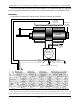
An EFB-Quad or PID-Quad controller is used to control up to four independent servo
loops. Each of these loops consists of a servo valve or motor controller, an actuator
(hydraulic or pneumatic cylinder or electric motor), and a transducer (typically a 10 Kohm
variable resistor) linked to the actuator.
In operation, a control voltage (nominally 0 to 10 VDC) is sent to the EFB-Quad or PID-
Quad controller. The card’s circuitry compares this incoming voltage with the current
position of the actuator as sensed by the transducer.
The most common failure in animated figures which use EFB analog movements are
broken wires leading to the transducer. For that reason Gilderfluke's EFB-Quad and PID-
Quad controller were designed so that they only needs two wires to each transducer
(three are usually required) and it constantly checks the status of these wires. If there is a
wire break, it will immediately switch off that axis. When a break is sensed, or when power is
first applied to the EFB-Quad or PID-Quad controller, it will stay in the error condition for
approximately 10 seconds. This will keep circuits with loose wire connections from jumping
in and out of error condition.
There is a 'broken wire' indicator LED for each of the four channels in the EFB-Quad or
PID-Quad controller. If any of the circuits is in an error condition, then the 'error' LED will light.
This error signal can be be sent to a remote indicator or alarm through the optically
isolated ‘Error’ output. A remotely mounted LED or small relay can be used to indicate a
problem with the figure on a central indicator panel.
GILDERFLUKE & CO. • 205 SOUTH FLOWER ST. • BURBANK, CALIF. 91502-2102 • 818/840-9484 • FAX818/840-9485
4 of 12