
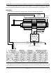
Manual

completely disconnected. Most valves have some sort of setscrews or other mechanical
adjustments which will allow you to center the valve until there is no movement in the cylinder. If
you can’t disconnect the valve from the feedback card, you can attach a voltmeter across the
valve outputs and position the movement until it stays at mid-stroke. Then mechanically adjust
the valve until the voltmeter reads zero volts.
The Null control on the PID-Quad is used to center valves that can not be adjusted
mechanically. It can also be used to offset movements that are so heavily loaded in one
direction that they move more slowly in one direction than the other.
The null control must be set to provide zero volts before any of the other controls have
been set. To do this, turn the P, I, D and Dither controls fully counter clockwise. Attach a meter
across the valve outputs for the channel being adjusted. Adjust the Null control until the meter
reads zero volts.
If your valve needs to be nulled electronically, then attach the valve and apply air or
hydraulic pressure. Adjust the Null control until the cylinder stays stationary (or nearly stationary).
6) Velocity Limit: This control limits the maximum amount the valve may open by limiting the
voltage that is sent to the valve.
Turning this control clockwise will increase its effect. Turning it counterclockwise reduces its
effect. When turned fully counter clockwise, it has no effect at all.
The Velocity control can be used to limit the speed of a movement by limiting the voltage
that can be sent to the valve. This has the same effect as electronically reducing the size of the
valve. You may want to limit the velocity of a movement for safety reasons (as when you just
don’t want a movement to move too fast), or by limiting the velocity of a movement, you may
be able to increase the gain of the movement to a point higher than you otherwise could. This
can give you a movement that follows the commanded position more sharply, albeit more
slowly at maximum speed.
7) Compliance Gain (PID-Quad only): This sets the gain of the compliance input. It is adjusted
interactively with the Compliance Depth control.
Turning this control clockwise will increase its effect. Turning it counterclockwise reduces its
effect. When turned fully counter clockwise, it has no effect at all. This should be done to turn
off the compliance if it is not being used.
8) Compliance Depth (PID-Quad only): This sets the length of time that a compliance input will
have an effect on the output. Increasing the Compliance depth will not only affect the length
of time that it has an effect, it will also increase the amount of effect that it has. It is adjusted
interactively with the Compliance Gain control.
Turning this control clockwise will increase its effect. Turning it counterclockwise reduces its
effect. When turned fully counter clockwise, it has no effect at all. This should be done to turn
off the compliance if it is not being used.
A green/red bicolor LED shows the compliance inputs and their effect on the outputs. A
compliance input is usually attached to a strain gauge or accelerometer. Voltage input ranges
that are acceptable are 0-5 or 0-10 volts. When the compliance input has a changing signal
applied to it, it will have a momentary effect on the output. This will then fade away over time
until it has no more effect. The amount of time the input effect takes to fade away is set using
the Compliance Depth control. The Compliance Depth and Compliance Gain both have an
effect on how much of an effect the compliance input has on the output.
When installing a compliance feedback element (either a strain gauge or accelerometer),
you have a 50%/50% chance of installing it backwards. The effect of the compliance inputs
can be reversed by moving the jumpers labeled ‘compliance inputs’. The jumpers can be
moved to either the ‘true’ or ‘inverted’ positions as needed.
GILDERFLUKE & CO. • 205 SOUTH FLOWER ST. • BURBANK, CALIF. 91502-2102 • 818/840-9484 • FAX818/840-9485
9 of 12