OPERATION AND INSTALLATION GUIDE FOR MODELS: SPS-120 & SPP-180 GILLETTE GENERATORS AUTOMATIC POWER SYSTEMS
TABLE OF CONTENTS Page Introduction, General Cautions, Warnings, & Danger Points ------------------3-6 Un-packing and Inspection of your Generator Set ------------------------------6-7 Pre-installation and Plot Planning of your Generator Set -----------------------7-9 Know your Gillette Generator Set----------------------------------------------------10 Know your Gillette Automatic Control System ------------------------------------11 Gaseous Dry Fuel System : Natural Gas (NG) ------------------------------
SAVE THESE INSTRUCTIONS THIS MANUAL CONTAINS IMPORTANT INSTRUCTIONS THAT MUST BE FOLLOWED DURING INSTALLATION, OPERATION, AND MAINTENANCE OF THIS GENERATOR SET AND ALL ASSOCIATED EQUIPMENT. Thoroughly read this operators manual before installing, operating, or servicing your generator set. Safe operation and best performance can be achieved only when this generator is operated and maintained properly. INTRODUCTION industry standards, and regulations.
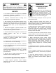
WARNING WARNING The engine exhaust from this product contains chemicals known to the state of California to cause cancer, birth defects, or other reproductive harm. STARTING BATTERY PRECAUTIONS ● For all safety reasons to the equipment, GILLETTE recommends installation, start-up and service be performed by experienced personnel. Starting batteries are not furnished with your generator set, but they are available through your installing contractor.
Breathing carbon monoxide will cause fatigue, headache, dizziness, vomiting, fainting, and in prolong conditions, even death. DANGER ELECTRICAL HAZARDS A generator produces dangerous electric voltages and can cause a fatal electric shock and will cause sudden illness, dizziness, and incoherent actions. ● Despite the safe design of this GILLETTE generator, operating it carelessly, neglecting its normal maintenance, or being ill informed of proper operations can cause possible serious injury or death.
must be installed at time of operation. WARNING ● If connected electrical items overheat, disconnect them immediately. FIRE OR EXPLOSION CONDITIONS Gaseous fuels such as natural gas (NG) and liquid propane (LP) are extremely explosive. Make sure the fuel supply system is installed in compliance with local and state fuel codes and regulations. Fuel leaks when ignited, can cause fire and explosion, resulting in harm or possible death.
GENERATOR CONTENTS The GILLETTE home generator set is supplied with the following components: ● Home generator system within soundproofed all weather metal enclosure (Depending on option choice, this can be an open set or a super-silent enclosure add). generator set. The automatic transfer switch is an optional selection and can be used with any model GILLETTE home generator set. All installation procedures, operating cautions, and warranties are responsibility of the separate manufacturers of the ATS.
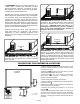
3) PREFERRED: Generator is mounted directly on a concrete slab, 4 inches thick, extending 6 inches beyond generator perimeter, and bolted in place. This method is for those locals with “high wind” considerations. (See Illustration #3) If gravel bed is chosen, its perimeter must be eight inches larger than generator base. Dig a rectangular area six inches deep, cover with landscape cloth (so drainage can take place) and fill with pea gravel or crushed stone.
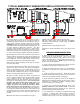
TYPICAL EMERGENCY GENERATOR INSTALLATION PRACTICES MINIMUM 5 FT (1) Drawing shows a typical gas utility approach on how to bring natural gas fuel to the gen-set. The fuel from utility is connected by dedicated fuel line, to the installed 4 ounce, 7” water column secondary regulator, inside gen-set housing. CAUTION: Consult your natural gas supplier about your meter size. Most meters must be replaced with a larger BTU size, due to larger demand of BTU’s from generator.
KNOW YOUR GILLETTE HOME GENERATOR Compare the following illustrations and individual component locations, with your actual GILLETTE home generator system. This will help familiarize yourself with the entire generator set. 3) 4) 5) 6) Control, Wiring, & Generator End 2) 7) Engine End 8) 1) Cool Air Input Cool Air Input 9) LEFT SIDE FACING ENGINE END WITH SERVICE PANEL REMOVED 1) Ground Wire to Ground Stake (Electrician) 6) Oil cooler.
KNOW YOUR SYSTEM CONTROL PANEL Compare the illustration with actual GILLETTE home generator system. 5) 1) 8 Point, LED diagnostic display panel. 2) #S-2 optional alarm system interface for fault detection. 2) 3) 3) TS1: Electrician’s connection terminals for 2-Point Remote Start/Stop Dry Contact Terminals. 4) 4) TS2: Electrician’s 120 VAC Utility Power connection terminals for powering optional equipment i.e.
THE GASEOUS DRY FUEL SYSTEM INSTALLATION the bend and cause a gas leak, causing a possible fire hazard. WARNING NATURAL GAS FUEL Propane (LPG) and natural gas (NG) is extremely flammable and explosive. Fire or explosion can cause serious burns or death. Required natural gas fuel pressure must be 6 to 8 inches water column (4 to 4½ ounces) and minimum 1000 BTU rating per cubic foot/hour NATURAL GAS CONSUMPTION AT FULL LOAD LPG is heavier than air and will settle in low areas.
EXAMPLE 2: A model SPP-180, 16 KW generator is to be installed 50 feet from gas meter. In reading the charts, Fig. 1 shows this model to require 280 cubic feet/hour (or 280,000 BTU/hr) gas volume to be delivered to generator. Figure 2 chart show this required 280 cu.ft. can not be delivered with a ¾” or 1” pipe. Only a 1¼” diameter pipe can safely deliver the 280 cu.ft. gas requirement, over a 50 foot distance.
LPG GAS FUEL This home generator system has been set up at the factory for natural gas fuel, unless it has been specifically ordered for vapor withdrawal liquid propane gas (LPG). This installation/operation guide will explain the factory LPG system. Additional information is available upon request for field conversion from one fuel to the other.
A flexible LPG fuel line is furnished for installation between the LPG fuel line & generator fuel input. CAUTION: Make sure this flexible fuel line is installed in a horizontal position, without bends. A bend of any kind, in this flexible line could lead to an eventual crack in the bend, causing a possible fuel leak. See Figure 6 for recommended installation. Make sure fuel line installation includes an on/off manual gas valve at both the LPG tank and at connection point of generator.
FOR LICENSED ELECTRICIAN’S USE, ONLY When hinged door on generator end of housing is un -locked and opened, the control panel is exposed. (see item 1, 8 point diagnostic display panel on page 11). An access panel, for electrician’s use only, is located at top of hinged door access. DANGER At engine end, behind bolted panel contains dangerous high voltage electricity. These voltages can cause a fatal electric shock and will cause sudden illness, dizziness, and incoherent actions.
BATTERIES CAN CAUSE DANGEROUS CHEMICAL BURNS NOTICE Dielectric grease should be used on battery lugs or posts to help in the prevention of normal corrosion. A battery can cause a chemical burn. Before working on a battery, follow safe procedures: Damage will result to generator controls, if battery cables are made in reverse connections. ● Wear full eye protection and protective clothing. Inspect, clean, or re-grease battery connections ever 60-90 days.
NOTE: For air temperatures below 32º F (0º C), it is highly recommended to replace oil with a synthetic oil, API SJ/CF 5W-30W. This allows for easier engine starting and better dry fuel engine performance during cold weather. Add necessary oil to bring level to “upper limit” on dipstick, replace dipstick and filler cap. “TEST” position will start the engine, but will not disconnect utility power from the transfer switch.
CARBURETION SYSTEMS FOR RESIDENTIAL SENTRY-PRO GEN-SETS BLANK CAP GAS HOSE TO ENGINE NG LP C.A.R.B AND EPA CARBURETION SYSTEMS FOR MODEL SPS-120 USING SUBARU ENGINES KN GAS REGULATOR GAS SOLENOID VALVE MODEL SPS-120 use the gas system as shown above. The KN gas regulator is used to regulate the gas flow by responding to pressure changes in the engine intake manifold. When the engine is shut down, with no demand for fuel, the “demand” secondary regulator stops all gas flow.
CAUTION main 2-pole, automatic circuit breaker (item “D” on control panel, page 11). Apply electric utility power BE EXTREMELY CAREFUL. YOU ARE READY TO TEST RUN A GENERATOR THAT HAS BOTH ELECTRIC SHOCK AND FLAMMABLE FUEL POTENTIAL HAZARDS. CHECK AND REVIEW ENTIRE INSTALLATION BEFORE START-UP. MAKE SURE THAT RATING OF TRANSFER SWITCH, MATCHES OR IS MORE THAN THE RATING OF THE EMERGENCY GENERATOR, IN VOLTS, PHASE, AND FREQUENCY. MISMATCHED SPECIFICATIONS WILL CAUSE WARNING PROCEED WITH CAUTION.
voltage and frequency at no load conditions. Typical no load test readings should be 230-245 volts at 61.061.5 hertz. After all meter tests are complete, return the “MODE SELECTOR” switch to the “OFF/RESET” position. The engine will then shut down. STEP 4: When all connections, adjustments, and tests are completed, and the automatic transfer switch is installed and wired, the standby generator system is ready to be placed on standby duty.
dipstick and oil fill cap to facilitate complete draining process. When oil is drained, replace dip stick, oil fill cap, oil hose drain cap and place hose in holding clip. OIL FILL: Replace oil with premium grade API SJ/10W-30 oil when ambient temperature is above 32º F (0º C). When temperature is below 32º F, use a synthetic premium grade, API SJ/CF5W-30W. This synthetic oil facilitates cold weather starting. Oil level should reach “upper limit” level on oil dipstick.
BASIC SERVICE TIPS/TROUBLE SHOOTING GUIDE BASIC SERVICE TIPS, TROUBLE SHOOTING AND NEW START-UP HELP, FOR YOUR GILLETTE STANDBY GENERATOR: A) ENGINE WILL NOT CRANK: • • • • • • BATTERY LEAD CONNECTIONS LOOSE OR CORRODED BATTERY CHARGE IS LOW OR DISCHARGED BATTERY CABLES REVERSED LOOSE CONNECTIONS IN WIRING HARNESS STARTER SOLENOID DEFECTIVE FUSE BLOWN IN STARTER WIRING B) ENGINE WILL CRANK BUT WILL NOT START: • • • • • • TOO LITTLE OR NO FUEL SUPPLY FUEL SOLENOID VALVE DEFECTIVE FUEL VALVES ARE NOT ENERG
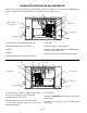
PAGE 24 GENERATOR END VIEW (C) ELECTRICAL & GROUND CONNECTION: THERE ARE TWO KNOCK-OUT HOLES ON THE LEFT HAND SIDE OF GENERATOR END. BOTH HOLES ARE FOR 3/4" CONDUIT. (B) DRY FUEL CONNECTION: LPG OR NAT. GAS CONNECTION IS LOCATED ON THE ENGINE END PANEL AS SHOWN. THERE IS A 3/4" THREADED MALE PIPE FOR CONNECTION. (A) (4) LIFTING HOLES IN BASE: 1-1/2" DIA. HOLES ARE INSTALLED IN BASE, FOR LIFTING EQUIPMENT. REMOVE PLASTIC COVERS IN THESE HOLES, AND RE-INSTALL COVERS WHEN GEN-SET IS IN PLACE.
PAGE 25 NOTE: NOUNTING BOLTS ARE POSITIONED INSIDE LOCKED CABINET, AS A DETERRENT TO THEFT. OUTSIDE MOUNTING BOLTS HAVE MADE THEFT TOO EASY WHEN GAS AND ELECTRIC LINES ARE REMOVED. NOTE: IF POLY BASE IN NOT USED, AND CEMENT PAD IS REQUIRED, THE 2-BOLTS IN CEMENT PAD MUST BE 5/16-18 AND EXITED OUT FROM CEMENT, 3-1/2". USE CEMENT PAD BOLT PLACEMENT DRAWING FOR POSITIONING THESE (2) BOLTS. INSTALL (2) BOLTS THRU HOLES IN POLY BASE, AS SHOWN, USING 5/16-18 HEX NUT TO LOCK BOLT IN PLACE.
PAGE 26 GENERATOR END VIEW (C) ELECTRICAL & GROUND CONNECTION: THERE ARE TWO KNOCK-OUT HOLES ON THE LEFT HAND SIDE OF GENERATOR END. BOTH HOLES ARE FOR 3/4" CONDUIT. (1) 1.5"Ø HOLE IN BASE FOR STUB-UP (B) DRY FUEL CONNECTION: LPG OR NAT. GAS CONNECTION IS LOCATED ON THE ENGINE END PANEL AS SHOWN. THERE IS A 3/4" THREADED PIPE COUPLING FOR CONNECTION. (A) (4) LIFTING HOLES IN BASE: 1-1/2" DIA. HOLES ARE INSTALLED IN BASE, FOR LIFTING EQUIPMENT.
PAGE 27 NOTE: NOUNTING BOLTS ARE POSITIONED INSIDE LOCKED CABINET, AS A DETERRENT TO THEFT. OUTSIDE MOUNTING BOLTS HAVE MADE THEFT TOO EASY WHEN GAS AND ELECTRIC LINES ARE REMOVED. NOTE: IF POLY BASE IN NOT USED, AND CEMENT PAD IS REQUIRED, THE 2−BOLTS IN CEMENT PAD MUST BE 7/16−18 AND EXITED OUT FROM CEMENT, 3−1/2". USE CEMENT PAD BOLT PLACEMENT DRAWING FOR POSITIONING THESE (2) BOLTS. INSTALL (2) BOLTS THRU HOLES IN POLY BASE, AS SHOWN, USING 7/16−18 HEX NUT TO LOCK BOLT IN PLACE.
PAGE 28 GND DC GND GND X DC 12VDC ONLY THREE 14GA CONTROL LEADS REQUIRED IF WIRED THIS WAY DYNAGEN VIGALANTE SERIES TRANSFER SWITCH GND DC JUMPER DETAIL ADD JUMPER *REQUIRED! DYNAGEN VIGALANTE SERIES TRANSFER SWITCH EATON RTC-100 CONTROLLER EATON EGSU "GREEN" SERIES TRANSFER SWITCH DC DC OFF / RESET STANDBY AC CONNECT TO COMMERCIAL POWER L1 AND NEUTRAL GND (MECHANICAL GROUND) GND GND DC OPTIONAL EQUIPMENT FOR GROUND STAKE ENCLOSURE GROUND CONNECT TO TRANSFER SW EMERGENCY SIDE A
PAGE 29 GND DC GND GND X DC 12VDC ONLY THREE 14GA CONTROL LEADS REQUIRED IF WIRED THIS WAY DYNAGEN VIGALANTE SERIES TRANSFER SWITCH GND DC JUMPER DETAIL ADD JUMPER *REQUIRED! DYNAGEN VIGALANTE SERIES TRANSFER SWITCH EATON RTC-100 CONTROLLER EATON EGSU "GREEN" SERIES TRANSFER SWITCH DC DC OFF / RESET STANDBY AC CONNECT TO COMMERCIAL POWER L1 AND NEUTRAL (MECHANICAL GROUND) GND GND GND DC OPTIONAL EQUIPMENT FOR GROUND STAKE ENCLOSURE GROUND CONNECT TO TRANSFER SW EMERGENCY SIDE A
SERVICE SCHEDULE SYSTEM COMPONENT OR PROCEDURE SEE PAGE CHECK CHANGE CLEAN TEST FREQUENCY AIR CLEANER X X R YEARLY OR EVERY 100 HRS. SPARK PLUG X X X YEARLY OR EVERY 250 HRS.
MAINTENANCE RECORD Use the following table to keep a record of all periodic and unscheduled maintenance and service. See Service Schedule DATE HOUR METER READING MAINTENANCE OR SERVICE PERFORMED Record the name, address, and phone number of your authorized GILLETTE service center.
Gillette Generators, Inc. 1340 Wade Drive Elkhart, IN 46514 Phone: 574-264-9639 Fax: 574-262-1840 E-mail: sales@gillettegenerators.com www.gillettegenerators.com Call for Tech Support: 1-866-537-4388 Email: service@gillettegenerators.