
Instruction Manual


PAGE 16
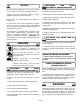
Electrician must remove (3) cap screws (see arrows)
and slide panel down 2 inches, then pull straight out
for complete removal. At this point, high voltage
wiring terminals are exposed. Replace panel by
positioning it 2” under roof, sliding it upwards until it
stops, then replacing (3) cap screws.
The high voltage access panels should only
be removed by experienced licensed
electricians, repair and service personnel,
and installers.
Electrical shock from mishandled
battery.
Toxic fumes from battery or engine
exhaust may be inhaled.
Hot surfaces may cause severe burns.
Explosions from battery or dry fuel
fumes being ignited by careless smoking or
sparks from mishandled tools.
At engine end, behind bolted panel
contains dangerous high voltage
electricity. These voltages can cause a
fatal electric shock and will cause sudden illness,
dizziness, and incoherent actions. Only experienced
licensed electricians and authorized service
technicians should have access to this high voltage
area.
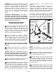
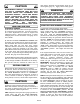
The 12 VDC battery is not furnished with the standby
generator set. The generator can be installed in a
wide range of temperatures and climate conditions.
As climates get colder, batteries loose their ability to
produce required power. Therefore, battery size
must be increased.
Climates that reach to a low of 30º F (-1.1 º C) can
achieve good generator operation with a 12 VDC, 45
amp hour battery. Climates that reach below this
temperature line should have a 55 amp/hour 12 VDC
battery.
CAUTION: All 12 VDC batteries will loose a certain
percent of their charge while in storage. It is very
important to test the battery voltage before it is
installed in generator and taken to jobsite. A fully
charged battery must test at 12.5 – 13.0 volts DC.
Also, the correct battery for models SPS-120 and SPP-
180 must have lug terminals to match lug battery
cables, for a bolt-together connection.
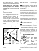
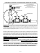
This generator is equipped with a battery tray, a
battery hold down strap and battery cables. Place the
selected fully charged battery with full electrolyte in
battery tray and secure with battery hold down
clamp.
Before connecting battery cables to battery, complete
the following steps:
1) Set the generator’s toggle switch to “OFF” position.
Remove the 20 amp fuse near the remote start/stop
terminal block (labeled “S” & “+”) on the back panel
of the control circuit (see these locations at “Know
Your Systems Control Panel” on page 11).
2) Turn off utility power supply to the previously
installed automatic transfer switch.
3) Battery cables are factory connected at the
generator points. Electrician should connect the red
battery cable (from engine starter solenoid point) to
battery post shown with “positive”, POS, or (+)
indicator. Connect the black battery cables (from
frame ground) to the battery.
DANGER
BATTERY SELECTION & INSTALLATION
WARNING
FOR LICENSED ELECTRICIAN’S USE, ONLY
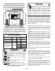
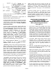
When hinged door on generator end of housing is un
-locked and opened, the control panel is exposed.
(see item 1, 8 point diagnostic display panel on page
11). An access panel, for electrician’s use only, is
located at top of hinged door access.
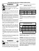
TIGHTENING TORQUE REQUIREMENTS FOR
FIELD WIRING TERMINALS
FIELD CONNECTION SCREW SIZE
WIRE SIZE
AWG
TORQUE
(LB/IN)
TS1
REMOTE START WIRES
#6 14 12
COMMERCIAL POWER #6 14 12
TS2 GENERATOR
OUTPUT & EXTERNAL
GROUND LUG
18-10 20
8 25
6-3 35
2 40
LUG TYPE
CONNECTOR
HIGH TEMPERATURE
ENGINE MONITOR
OVER CRANK
OVER SPEED
ENGINE RUNNING
UNDER SPEED / FAIL
LOW OIL
NOT IN STANDBY
LOW BATTERY
MODE SELECTOR
TEST
OFF / RESET
STANDBY
SenDEC
ON
ON
50 AMP
CIRCUIT BREAKER
HINGED DOOR REMOVED
FOR CLARITY
(PANEL COVERING HIGH
VOLTAGE TERMINALS)