Installation and Operating Instructions Door Station Stainless 2551 20, 2552 20, 2553 2554 20, 2556 20, 2558 2559 20, 2560 20, 2562 Steel Video 20 20 20
Table of contents Device description ......................................................................................................5 Function range of the colour camera...........................................................................6 Coverage range of the colour camera .........................................................................6 Selection of the installation site ..................................................................................7 Installing panel box ........
Device description The Door Station Stainless Steel Video is a pre-assembled, vandalism-protected door station with colour camera for the Gira door communication system. The front plate of high-quality V2A stainless steel with a thickness of 3 mm is especially robust. The call buttons are also made of durable stainless steel. The illuminated inscription labels are covered by a fully secured and flameproof glass plate.
Function range of the colour camera The colour camera of the flush-mounted door station has the following product features: Automatic day/night switching The camera switches from daytime mode (colour presentation) to night mode (black and white presentation) and back again at an ambient brightness of 1 Lux. Due to the high degree of light sensitivity in night mode, good presentation results are achieved even with poor lighting conditions (to 0.1 Lux).
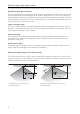
Selecting the installation site The selection of the installation site and good illumination are critical for good picture quality. No backlighting Do not point the colour camera towards strong backlighting, such as streetlamps or yard illumination. Prevent strong sunlight from hitting the lens. Picture background Avoid pointing the camera towards extremely bright image backgrounds and backgrounds with strong contrasts.
Installing panel box Attention Installation and mounting of electrical devices may only be carried out by a qualified electrician. 1. Select a suitable installation site and chisel an opening in the wall. 2. If necessary, mount the included wall anchor. Note the following information when mounting the panel box: • Ensure installation position is correct. (Note the "TOP" labelling). • The panel box must be installed level.
4. Mount the included plaster protection. 5. Plaster the wall. 6. Carefully remove the plaster and take out the plaster protection.
Installing front panel 1. Insert the locking plate flushly into the panel box. i Insert locking plate evenly The locking plate must not be twisted while being installed into the panel box and must not be under tension. Push the locking plate inwards until the plastic brackets touch the wall. 2. Fasten the locking plate with the 4 Allen bolts and locking washers included. In order to guarantee a secure fastening of the front panel later, the Allen bolts must be firmly tightened. 3.
5. Pull the front panel from the mounting retainers (1.) and fold these in (2.). 2. 1. 6. Position the (lower) fastening bolt(s) of the front panel to "Close". Open Close 7. Mount the front panel onto the guide bolts and press it on until the upper and lower fastening bolts engage. Start-up Once all of the devices (door and home stations, control device etc.) have been installed, the door communication system can be started up.
Setting range of coverage of colour camera 1. Remove the colour camera from the back of the front panel of the Door Station Stainless Steel: Loosen both screws of the attachment profile for this purpose. 2. Remove the camera cover plate from the demounted colour camera. 3. Slightly loosen both Torx screws to the left and right of the camera lens. i Do not take out the screws completely! When adjusting the lens carrier, it is sufficient to slightly loosen the screws.
Opening of Door Station Stainless Steel The included opening tool is required for opening the Door Station Stainless Steel. 1. Turn the (lower) fastening bolt(s) with the opening tool to "Open". Single-column door stations have one lower fastening bolt, double-column door stations have two lower fastening bolts. The position of the fastening bolts is shown via small recesses on the lower side of the front panel.
Replacing inscription label Inscription labels For labelling the Gira Door Station Stainless Steel, use only Gira inscription labels. The transparent plastic labels are non-fading, weather-resistant and wrinkle-free. With the included release code, inscription labels for the first labelling are available free at www.marking.gira.com cli ck 1. Unlock the call button with the enclosed plastic key: twist the plastic key anti-clockwise until it engages. 120° 2.
5. Position the inscription label underneath the clips of the inscription label carrier. 6. Slide in the inscription label carrier again. At the same time, position the inscription label with your finger. click ustermann click 7. Release the call button: To do this, press in the plastic key slightly and turn it clockwise until the call button is released from the lower position. 8. Lock the call button: To do this, turn the plastic key clockwise again until it engages. ustermann 9.
Operation Volume setting The volume can be set separately at each door station. The volume setting must be made by two people. 1. Press the "Systemprogr." button on the control device for 3 sec. to start programming mode. 1x M. Meier 2. Briefly press a previously assigned call button at the door station. 3. The second person accepts the door call at the home station (via receiver or speech button) and starts speaking. 1x 4. Briefly press the call button again at the door station. M.
Technical data Connections: 2 2 2 1 2 screw terminals for 2-wire bus screw terminals for additional supply system bus connector strips (6-pole) video connector strip (2-pole) sabotage contact screw terminals Power supply: 2 cameras via video control device 3.
Warranty The warranty is provided in accordance with statutory requirements via the specialist trade. Please submit or send faulty devices postage paid together with an error description to your responsible salesperson (specialist trade/installation company/electrical specialist trade). They will forward the devices to the Gira Service Center.
Postfach 1220 42461 Radevormwald Deutschland Tel +49 (0) 21 95 / 602 - 0 Fax +49 (0) 21 95 / 602 - 191 www.gira.de info@gira.de 10 41 09 25 20/11 Gira Giersiepen GmbH & Co.