Item #1000 017 514 Model #2623NNHD USE AND CARE GUIDE OVER-THE-TOILET SPACESAVER Questions, problems, missing parts? Before returning to the store, call Glacier Bay Customer Service 8 a.m. - 6 p.m., EST, Monday - Friday 1-855-HD-GLACIER HOMEDEPOT.COM THANK YOU We appreciate the trust and confidence you have placed in Glacier Bay through the purchase of this over-the-toilet spacesaver. We strive to continually create quality products designed to enhance your home.
Table of Contents Table of Contents. . . . . . . . . . . . . . . . . . . . . . . . . . . . . . . . . . . . 2 Safety Information. . . . . . . . . . . . . . . . . . . . . . . . . . . . . . . . . . . 2 Warranty. . . . . . . . . . . . . . . . . . . . . . . . . . . . . . . . . . . . . . . . . . . 2 Pre-Installation. . . . . . . . . . . . . . . . . . . . . . . . . . . . . . . . . . . . . . 3 Planning Installation . . . . . . . . . . . . . . . . . . . . . . . . . . . . . . . . 3 Package Contents . . . . . . . . .
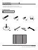
Pre-Installation PLANNING INSTALLATION □□ Please identify all the parts and hardware pieces before you begin. □□ When laying out the parts, place them on a soft surface to prevent scratching. HARDWARE INCLUDED NOTE: Hardware shown to actual size. AA BB CC GG FF EE Part Description Quantity AA Large screw 8 BB Medium screw 6 CC Small screw 4 DD End cap 8 EE Feet 4 FF Mounting screw 2 GG Wall anchor 2 HH Hex key 1 DD HH 3 HOMEDEPOT.
Pre-Installation (continued) PACKAGE CONTENTS A C D B C B D B E E H G G F Part F Description Quantity A Top piece 1 B Shelf 3 C Front tube 2 D Rear tube 2 E Leg 2 F Front leg extension 2 G Rear leg extension 2 H Bottom brace 1 4
Installation (continued) 1 Connecting the legs to the leg extensions NOTE: Be sure to orient the legs (E) so that the screw holes for the small screws (CC) are located on the back. E □□ Fasten front leg extensions (F) to the front of the legs (E), using the small screws (CC). back of legs assembly □□ Fasten rear leg extensions (G) to the rear of the legs (E), using the small screws (CC). CC G F 2 Inserting the end caps □□ Insert the end caps (DD) into the front and rear leg extensions (F and G).
Installation (continued) 3 Connecting the front and rear tubes to the legs NOTE: Be sure to orient the front tube (C) so that the end with the “dimpled” hole is on the top. D C □□ Fasten a front tube (C) and a rear tube (D) to each leg assembly. back of legs assembly 4 D Attaching the shelves to the leg assembly AA C NOTE: The crosswires should be on the bottom of the shelf. BB □□ Fasten two shelves (B) to the rear tubes (D) using the large screws (AA).
Installation (continued) 5 Connecting the top piece to the rear tubes A D □□ Insert the top piece (A) into the top rear tubes (D). D back of legs assembly 6 B Connecting the shelf to the assembly □□ Fasten the shelf (B) to the assembly, using the large and medium screws (AA and BB). BB AA 7 HOMEDEPOT.COM Please contact 1-855-HD-GLACIER for further assistance.
[Heading goes here] Installation (continued) 7 DD Attaching the end caps and feet to the assembly □□ Insert end caps (DD) into front tubes (C) and top piece (A). A □□ Insert the adjustable feet (EE) in the bottom of the front and rear leg extensions (F and G) and adjust, using the hex key (HH). F and G C EE 8 Attaching the brace to the assembly □□ Place the unit in the desired location. □□ Attach the bottom brace (H) to the rear leg extensions (G), using the large screws (AA).
[Heading goes here] Installation (continued) 9 Mounting the unit to the wall NOTE: For safety reasons, it is imperative that this unit be mounted to the wall. NOTE: Before cutting, drilling or hammering into any wall surface, verify the location of electrical, plumbing and gas lines. Cutting any of these may cause serious injury. □□ Mark mounting points on the wall through the holes in the rear tubes of the unit.
Questions, problems, missing parts? Before returning to the store, call Glacier Bay Customer Service 8 a.m. - 6 p.m., EST, Monday - Friday 1-855-HD-GLACIER HOMEDEPOT.COM Retain this manual for future use.
Item N.°1000 017 514 Modelo N.°2623NNHD GUÍA DE USO Y CUIDADO ORGANIZADOR DE ESPACIO SOBRE INODORO ¿Tiene preguntas, problemas, le faltan piezas? Antes de regresar a la tienda, llame al Servicio al Cliente de Glacier Bay de 8 a.m. — 6 p.m, Hora Estándar del Este, de lunes a viernes 1-855-HD-GLACIER HOMEDEPOT.COM GRACIAS Agradecemos la confianza que ha depositado en Glacier Bay a través de la adquisición de esta barra organizadora Premium.
Tabla de contenido Tabla de contenido. . . . . . . . . . . . . . . . . . . . . . . . . . . . . . . . . . . 2 Información de seguridad . . . . . . . . . . . . . . . . . . . . . . . . . . . . . 2 Garantía. . . . . . . . . . . . . . . . . . . . . . . . . . . . . . . . . . . . . . . . . . . 2 Pre-instalación. . . . . . . . . . . . . . . . . . . . . . . . . . . . . . . . . . . . . . 3 Planificación de la instalación. . . . . . . . . . . . . . . . . . . . . . . . . 3 Contenido del paquete. . . . . . . . . . . . .
Pre-instalación PLANIFICACIÓN DE LA INSTALACIÓN □□ Identifique todas las piezas y las piezas de tornillería antes de comenzar. □□ Al esparcir las partes, colóquelas sobre una superficie suave para evitar que se rayen. ELEMENTOS INCLUIDOS NOTA: La tornillería se ilustra en su tamaño real.
Pre-instalación (continuación) CONTENIDO DEL PAQUETE C A D B C B D B E E H G G F Pieza F Descripción Cantidad A Pieza superior 1 B Repisa 3 C Tubo delantero 2 D Tubo posterior 2 E Pata 2 F Extensión de pata delantera 2 G Extensión de pata posterior 2 H Soporte inferior 1 4
Instalación (continuación) 1 Conexión de las patas a las extensiones de las patas NOTA: Asegúrese de orientar las patas (E) de modo que los orificios de los tornillos para los tornillos pequeños (CC) estén localizados en la parte posterior. E □□ Fije las extensiones de las patas delanteras (F) al frente de las patas (E), usando los tornillos pequeños (CC).
Instalación (continuación) 3 Conexión de los tubos delanteros y posteriores de las patas NOTA: Asegúrese de orientar el tubo delantero (C) de modo que el extremo con el orificio con una “depresión” esté arriba. D C □□ Fije el tubo delantero (C) y un tubo posterior (D) a cada ensamble de pata. parte posterior de ensamble de patas 4 D Fijación de las repisas al ensamble de patas AA C NOTA: El centro de la equis debe estar en la parte inferior de la repisa.
Instalación (continuación) 5 Conexión de la pieza superior a los posteriores A D □□ Inserte la pieza superior (A) dentro de los tubos posteriores superiores (D). D parte posterior de ensamble de patas 6 B Conexión de la repisa al ensamble □□ Fije la repisa (B) al ensamble, usando los tornillos grandes y medianos (AA y BB). BB AA 7 HOMEDEPOT.COM Contáctese con 1-855-HD-GLACIER para recibir ayuda adicional.
[Heading goes here] Installation (continued) 7 DD Fijación de las cubiertas terminales y apoyos al ensamble □□ Inserte las cubiertas terminales (DD) dentro de los tubos delanteros (C) y de la pieza superior (A). A □□ Inserte los apoyos regulables (EE) en la parte inferior de las extensiones de las patas delanteras y posteriores (F y G) y ajústelos, usando la llave hexagonal (HH). FyG C EE 8 Fijación del soporte al ensamble □□ Coloque la unidad en el lugar deseado.
[Heading goes here] Installation (continued) 9 Montaje de la unidad a la pared NOTA: Por razones de seguridad, es fundamental que esta unidad sea montada a la pared. NOTA: Antes de cortar, taladrar o martillar cualquier superficie de pared, verifique la ubicación de los conductos eléctricos y las tuberías de agua y gas. Si interfiriese con cualquiera de estas, se podrían causar lesiones graves.
¿Tiene preguntas, problemas, le faltan piezas? Antes de regresar a la tienda, llame al Servicio al Cliente de Glacier Bay de 8 a.m. — 6 p.m, Hora Estándar del Este, de lunes a viernes 1-855-HD-GLACIER HOMEDEPOT.COM Conserve este manual para uso futuro.