Model #67369-0001 USE AND CARE GUIDE PULL-DOWN KITCHEN FAUCET Questions, problems, missing parts? Before returning to the store, call Glacier Bay Customer Service 8 a.m. - 6 p.m., EST, Monday - Friday 1-855-HD-GLACIER HOMEDEPOT.CA THANK YOU We appreciate the trust and confidence you have placed in Glacier Bay through the purchase of this kitchen faucet. We strive to continually create quality products designed to enhance your home.
Table of Contents Safety Information ....................................2 Warranty ...................................................2 Pre-Installation .........................................3 Planning Installation ..............................3 Tools Required .......................................3 Package Contents ..................................4 Installation ................................................5 Operation...................................................9 Care and Cleaning ........
Pre-Installation PLANNING INSTALLATION Before beginning the installation of this product, ensure all parts are present. Compare parts with the Package Contents section. If any part is missing or damaged, do not attempt to install the product. TOOLS REQUIRED Safety goggles (2) Supply lines Phillips screwdriver CO Silicone LI Flashlight SI Hex wrench (Hex key) NE Adjustable wrench Basin wrench 3 HOMEDEPOT.CA Please contact 1-855-HD-GLACIER for further assistance.
Pre-Installation (continued) PACKAGE CONTENTS A K L F O M G I H N B J C D E Part Quantity Part A Faucet assembly Description 1 I Description Weights Quantity B Plastic washer 1 J Quick connector 1 Pump 1 1 1 C Metal washer 1 K D Nut 1 L Body assembly E Screw 2 M Nut 1 F Flange 1 N Bottle 1 O Soap dispenser 1 G Escutcheon 1 H Gasket 1 4
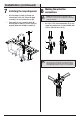
Installation 1 Preparing for installation 2 Installing the faucet assembly CAUTION: Always turn off the water supply before removing an existing faucet or replacing any part of a faucet. Open the faucet handle to relieve water pressure and ensure that the water is completely shut off. □ □ Shut off the water supply. Before installation, remove the quick connector (J) from the free end of the hose by unscrewing it in a counterclockwise direction. □ Unscrew the nut (D), and remove the washers (B & C).
Installation (continued) 3 Installing the faucet assembly 4 Securing the faucet assembly NOTE: This step is for escutcheon installation (optional). If the escutcheon will not be used, install the faucet assembly as described in step 2. □ Place the escutcheon (G) and the gasket (H) on the bottom of the new faucet assembly (A). □ Retract the hose (1) up through the faucet body, until the hose fitting is flush with the bottom of the shank (2). Do not pull the hose fitting past the shank.
Installation (continued) 5 Attaching the quick connector to the hose □ After inserting the hose through the hole in the sink surface, reattach the quick connector (J) by screwing it onto the threaded end of the hose (1) in a clockwise motion. Hand tighten only. the quick connector 6 Attaching to the receiving block □ Push the quick connector (J) firmly upward and attach it to the receiving block (1). Pull down moderately to ensure the connection has been made.
Installation (continued) 7 8 Installing the soap dispenser □ Insert the body assembly (L) through the selected hole in the sink. Secure the body assembly (L) to the sink with the nut (M). □ From under the sink, screw the bottle (N) onto the body assembly (L) shank. Insert the pump (K) down into the body assembly (L). Making the waterline connections NOTE: The hot side inlet tube is indicated by a label. If the label is not present, the hot supply tube is the longer of the two inlet tubes.
Operation 1 Flushing and checking for leaks IMPORTANT: After installation is completed, turn on the hot and cold water supply. Check for leaks. □ Pull the hose assembly out of the spout and remove the spray head by unscrewing it from the hose in a counterclockwise direction. Be sure to hold the end of the hose down into the sink and turn the faucet on to the warm position where it mixes hot and cold water. □ Flush the water lines for one minute.
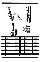
Service Parts *Specify Finish 2 1 3 19 4 5 6 22 20 7 8 15 21 23 24 9 10 25 18 11 12 13 14 Part Description 16 17 Part Number Part Description 1 Handle RP13249* 14 Screw Part Number RP50004 2 Set screw RP50002 15 Spray head and Hose RP38197* 3 Wearable ring RP64182 16 O-ring RP60089 4 Wearable ring RP64183 17 Weights RP70223 5 O-ring RP60042 18 Quick connector RP70429 6 O-ring RP60096 19 Pump kit RP46022 7 O-ring RP60097 20 Flange kit RP46043* 8 Cartrid
Questions, problems, missing parts? Before returning to the store, call Glacier Bay Customer Service 8 a.m. - 6 p.m., EST, Monday - Friday 1-855-HD-GLACIER HOMEDEPOT.CA Retain this manual for future use.
Modèle n°67369-0001 GUIDE D'UTILISATION ET D'ENTRETIEN ROBINET DE CUISINE RÉTRACTABLE Questions, problèmes, pièces manquantes? Avant de retourner au magasin, appelez le service à la clientèle de Glacier Bay de 8h à 18h, HNE, du lundi au vendredi 1-855-HD-GLACIER HOMEDEPOT.CA MERCI Nous vous remercions d'avoir fait confiance à Glacier Bay en achetant ce robinet de cuisine. Nous nous efforçons en permanence de créer des produits de qualité conçus pour perfectionner votre maison.
Table des matières Consignes de sécurité ............................13 Garantie...................................................13 Pré-installation .......................................14 ................14 Outils requis .........................................14 Contenu de l’emballage .......................15 Installation ..............................................16 Utilisation ................................................20 Entretien et nettoyage ............................
Pré-installation PLANIFICATION DE L’INSTALLATION Avant de commencer l’assemblage de ce produit, assurez-vous que toutes les pièces sont présentes. Comparez les pièces avec la liste du Contenu de l’emballage. Si une pièce est manquante ou endommagée, ne tentez pas d’assembler ce produit. OUTILS REQUIS Lunettes de protection Tournevis cruciforme Clé hexagonale Silicone Lampe de poche SI LI CO NE Clé à molette Conduites d'alimentation Clé pour lavabo 14 HOMEDEPOT.
Pré-installation (suite) CONTENU DE L'EMBALLAGE A K L F O M G I H N B J C D E Pièce Quantité Pièce A Description Robinet 1 I Pesées 1 B Rondelle en plastique 1 C Rondelle en métal 1 J Raccord à branchement rapide 1 D Écrou 1 K Pompe 1 E Vis 2 L Assemblage du corps 1 F Bride 1 M Écrou 1 Flacon 1 Distributeur de savon 1 G Rosace 1 N H Joint d'étanchéité 1 O 15 Description Quantité
Installation 1 2 Préparation en vue de l'installation ATTENTION : Coupez l’alimentation en eau CAUTION: Always turntoujours off the water supply before avant d’enlever un robinet ou de any remplacer removing an existing faucetexistant or replacing part of a n’importe quelle robinet. Ouvrezwater la poignée du faucet. Open the partie faucetdu handle to relieve pressure robinet pourthat libérer pression de l’eau et vous and ensure the la water is completely shut off.
Installation (suite) de l'ensemble de solidement l'ensemble 4 Fixer 3 Installation robinetterie de robinetterie REMARQUE : Cette étape est pour l'installation de la rosace (facultatif). Si vous n'utilisez pas la rosace, installez l'ensemble de robinetterie comme décrit dans l'étape 2. □ Placez la rosace (G) et le joint d'étanchéité (H) sur le bas du nouvel ensemble de robinetterie (A).
Installation (suite) 5 □ 6 Attacher le raccord à branchement rapide au tuyau Après avoir inséré le tuyau flexible dans le trou de la surface de l'évier, vissez de nouveau le raccord à connexion rapide (J) sur l'extrémité filetée du tuyau (1) flexible en tournant dans le sens des aiguilles d'une montre. Serrez à la main uniquement. Attacher le raccord à branchement rapide au bloc récepteur □ Poussez fermement le raccord à branchement rapide (J) vers le haut et attachez-le au bloc récepteur (1).
Installation (suite) 7 Installation du distributeur de savon □ Insérez le corps (L) dans le trou choisi de l'évier. Fixez le corps (L) à l'évier à l'aide d'un écrou (M). □ Sous l'évier, vissez le flacon (N) sur la tige du corps (L). Insérez la pompe (K) dans le corps assemblé (L). des conduites 8 Branchement d'alimentation en eau REMARQUE : Le tuyau d'arrivée de l'eau chaude est indiqué par une étiquette.
Utilisation 1 Purge et recherche de fuites IMPORTANT : Une fois l'installation terminée, ouvrez l’alimentation en eau chaude et en eau froide. Vérifiez s’il y a des fuites. □ Retirez du bec l’assemblage du tuyau, puis retirez du tuyau la tête de pulvérisation en la tournant dans le sens contraire des aiguilles d’une montre. Tout en veillant à maintenir l'extrémité du tuyau flexible dans l'évier, mettez la poignée du robinet en position tiède où l'eau chaude et l'eau froide se mélangent.
Pièces de rechange *Spécifiez un fini 2 1 3 19 4 5 6 22 20 7 8 15 21 23 24 9 10 25 18 11 12 13 14 Pièce Description 16 17 Numéro de pièce 1 Manette RP13249* 2 Vis de pression RP50002 3 Bague d'étanchéité 4 5 6 Joint torique RP60096 7 Joint torique 8 Cartouche Pièce Description Numéro de pièce 15 Tête et tuyau de pulvérisation RP38197* RP64182 16 Joint torique RP60089 Bague d'étanchéité RP64183 17 Pesées RP70223 Joint torique RP60042 18 Raccord à branchement rapid
Questions, problèmes, pièces manquantes? Avant de retourner au magasin, appelez le service à la clientèle de Glacier Bay de 8h à 18h, HNE, du lundi au vendredi 1-855-HD-GLACIER HOMEDEPOT.CA Conservez ce manuel pour référence future.