SKU# Model# 67513W-6401 1001700852 INSTALLATION AND CARE GUIDE TWO-HANDLE LAVATORY FAUCET Questions, problems, missing parts? Before returning to the store, call Glacier Bay Customer Service 8 a.m. - 7 p.m., EST, Monday - Friday 9 a.m. - 6 p.m., EST, Saturday 1-855-HD-GLACIER (1-855-434-5224) HOMEDEPOT.COM/GLACIERBAY THANK YOU We appreciate the trust and confidence you have placed in Glacier Bay through the purchase of this lavatory faucet.
Table of Contents Important Information ..............................2 Warranty ...................................................2 Pre-Installation .........................................2 Planning Installation ..............................2 Tools and Hardware Required ...............2 Package Contents ..................................3 Installation ................................................4 Operation...................................................8 Care and Cleaning ......................
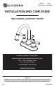
Pre-Installation (continued) PACKAGE CONTENTS Faucet Assembly Drain Assembly M A D* K E* L B F* G* C J I H* NOTE: *Items D - H come pre-assembled. Part Description Quantity Part Description Quantity Drain body 1 A Faucet 1 H B Gasket 1 I Joint 1 C Mounting nut 2 J Horizontal rod 1 D Pop up stopper 1 K Lift rod strap 1 E Drain flange 1 L Clip 1 F Rubber washer 1 M Lift rod 1 G Lock nut 1 3 HOMEDEPOT.
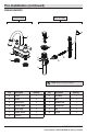
Installation 1 Installing the faucet assembly 2 Preparing the pop-up assembly CAUTION: Always turn off the water supply before removing an existing faucet or replacing any part of a faucet. Open the faucet handle to relieve water pressure and ensure that the water is completely shut off. □ Shut off the water supply. Remove the old faucet. □ Clean the mounting surface. □ Ensure the gasket (B) is on the bottom of the new faucet (A). □ Place the faucet (A) through the mounting holes in the sink.
Installation (continued) 3 Installing the drain body the stopper and 4 Installing horizontal rod □ Apply silicone sealant (not included) under the drain flange (E) and place the drain flange (E) into the drain hole of the sink. □ From underneath the sink, screw the drain body (H) onto the drain flange (E). Ensure that the opening (1) for the ball rod on the drain body (H) faces towards the rear of the sink. □ □ □ Tighten the rubber washer (F) and lock nut (G) on the drain body (H).
Installation (continued) the horizontal rod 5 Attaching and strap M □ Slide the lift rod (M) through the faucet (A). □ Press the rod (J) down to ensure the stopper (D) is in the maximum open position. □ Slide the clip (L) upward, adjust the location of the lift rod strap (K) to the appropriate height and insert the horizontal rod (J) with the correct hole of the lift rod strap (K). □ A 1 Move the lift rod strap (K) in or out to choose an appropriate location.
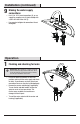
Installation (continued) 7 Adjusting the length of lift rod strap □ If the pop up lift rod strap (K) is interfering with your installation, as shown in the Fig 1, the lift rod strap (K) can be cut shorter. □ Once you have identified the proper hole in the lift rod strap (K) that is necessary for your installation, you may cut off the bottom portion (1) of the lift rod strap (K) by snapping off with pliers or cut off with a saw at the cutting point (2), as shown in the Fig 2.
Installation (continued) the water supply 9 Making connections □ □ Use 1/2 in. I.P.S. faucet connections (2), or use supply line coupling nuts (3) (not included) with a 3/8 in. O.D. ball-nose riser (1). Use wrenches to tighten the connections. Do not overtighten. 1 3 2 Operation 1 Flushing and checking for leaks IMPORTANT: After installation is complete, remove the aerator from the faucet (A) to flush the water lines. Do not lose the mesh washer (1).
Care and Cleaning □ To clean, wipe down with a damp cloth and dry with a towel. □ Do not use abrasive cleaners, steel wool, or harsh chemicals when cleaning this faucet, or the warranty will be voided. Troubleshooting NOTE: Refer to the service parts section in this manual for a detailed drawing showing the location of the parts listed below. Problem Possible Cause There are leaks from the handle. The bonnet nut has come loose and/or the washer is dirty or damaged. □ Tighten the bonnet nut.
Service Parts 2 16 3 11 1 4 12 13 5 14 6 7 Faucet ID tags can be found by removing the hot water handle 8 9 17 15 10 Part Part Number Part Description Part Number Index H RP10001* 10 Mounting nut RP56001 2 Index C RP10002* 11 Aerator RP30218* 3 Screw RP50005 12 Washer RP70077 1 Description 4 Handle RP13246* 13 Clip RP70106 5 Inverter RP64044 14 O-ring RP60008 6 Bonnet nut RP70193 7 Washer RP64123 15 ClickInstall™ drain assembly RP40228* 8 Cartridge
Questions, problems, missing parts? Before returning to the store, call Glacier Bay Customer Service 8 a.m. - 7 p.m., EST, Monday - Friday 9 a.m. - 6 p.m., EST, Saturday 1-855-HD-GLACIER (1-855-434-5224) HOMEDEPOT.COM/GLACIERBAY Retain this manual for future use.
Modelo núm. SKU núm. 67513W-6401 1001700852 GUÍA DE USO Y MANTENIMIENTO GRIFO PARA LAVAMANOS, DE DOS LLAVES ¿Problemas, preguntas o piezas faltantes? Antes de regresar a la tienda, llama al servicio al cliente de Glacier Bay de lunes a viernes entre 8 a.m. y 7 p.m. y los sábados entre 9 a.m. y 6 p.m.(hora estándar del Este) 1-855-HD-GLACIER (1-855-434-5224) HOMEDEPOT.COM/GLACIERBAY GRACIAS Agradecemos la confianza que has depositado en Glacier Bay al comprar este grifo para lavamanos.
Tabla de contenido Información importante .........................13 Garantía...................................................13 Pre-instalación .......................................13 Planificación de la instalación .............13 Herramientas y herrajes necesarios ....13 Contenido del paquete .........................14 Instalación ..............................................15 Funcionamiento ......................................19 Cuidado y limpieza ................................
Pre-instalación (continuación) CONTENIDO DEL PAQUETE Ensamblaje del drenaje Ensamblaje de la mezcladora M A D* K E* L B F* G* C J I H* NOTA: *Los artículos D - H vienen preensamblados.
Instalación instalar el ensamblaje preparar el ensamblaje 1 Cómo 2 Cómo del grifo emergente PRECAUCIÓN: Cierra siempre el suministro de agua antes de quitar un grifo existente o reemplazar cualquier pieza de un grifo. Abre la llave del grifo para liberar la presión de agua y asegúrate de que el suministro de agua esté completamente cerrado. □ Cierra el suministro de agua. Retira el grifo anterior. □ Limpia la superficie de montaje.
Instalación (continuación) instalar el cuerpo del instalar el tapón y la 3 Cómo 4 Cómo drenaje varilla horizontal □ Aplica sellador de silicona (no incluido) debajo de la brida del drenaje (E) y coloca ésta dentro del orificio de drenaje del lavabo. □ Desde la parte inferior del lavabo, enrosca el cuerpo del drenaje (H) en la brida del drenaje (E). Asegúrate de que la abertura (1) para la varilla de bola del cuerpo del drenaje (H) esté frente a la parte posterior del lavabo.
Instalación (continuación) instalar la varilla 5 Cómo horizontal y la correa □ Desliza la varilla de elevación (M) a través del grifo (A). □ Presiona hacia abajo la varilla (J) para garantizar que el tapón (D) esté abierto completamente. □ Desliza la presilla (L) hacia arriba, ajusta la ubicación de la correa de la varilla de elevación (K) a la altura adecuada e inserta la varilla horizontal (J) con el orificio correcto de la varilla de elevación (K).
Instalación (continuación) 7 Cómo ajustar el largo de la correa de la varilla de elevación □ Si la correa de la varilla de elevación (K) sobresale tanto que interfiere con tu instalación, como se muestra en la Fig 1, la varilla de elevación (K) puede recortarse.
Instalación (continuación) hacer las conexiones 9 Cómo del suministro de agua □ Usa conexiones de grifos de 1/2" IPS (2) o tuercas de acoplamiento de líneas de suministro (3) (no incluidas) con un tubo montante de bola de diámetro exterior de 3/8" (1). □ Usa llaves para apretar las conexiones. No aprietes demasiado.
Cuidado y limpieza □ Para limpiar, usa un paño húmedo y seca con una toalla. □ No uses limpiadores abrasivos, esponjas de alambre o productos químicos fuertes para limpiar esta mezcladora, pues ello anulará la garantía. Solución de problemas NOTA: Consulta la sección de piezas de repuesto de este manual para ver un dibujo detallado que muestra la ubicación de las piezas enumeradas a continuación. Problema Posible causa Hay filtración por el maneral.
Piezas de repuesto 2 16 3 11 1 4 12 13 5 14 6 7 Las etiquetas de identificación de la mezcladora pueden verse al quitar el maneral del agua caliente.
¿Problemas, preguntas o piezas faltantes? Antes de regresar a la tienda, llama al servicio al cliente de Glacier Bay de lunes a viernes entre 8 a.m. y 7 p.m. y los sábados entre 9 a.m. y 6 p.m.(hora estándar del Este) 1-855-HD-GLACIER (1-855-434-5224) HOMEDEPOT.COM/GLACIERBAY Conserva este manual para uso futuro.