Model# 67575W-6001 67575W-6004 SKU# 703464 703460 INSTALLATION AND CARE GUIDE TWO-HANDLE LAVATORY FAUCET Questions, problems, missing parts? Before returning to the store, call Glacier Bay Customer Service 8 a.m. - 7 p.m., EST, Monday - Friday 9 a.m. - 6 p.m., EST, Saturday 1-855-HD-GLACIER (1-855-434-5224) HOMEDEPOT.COM THANK YOU We appreciate the trust and confidence you have placed in Glacier Bay through the purchase of this lavatory faucet.
Table of Contents Safety Information ....................................2 Warranty ...................................................2 Pre-Installation .........................................2 Planning Installation ..............................2 Tools Required .......................................2 Package Contents ..................................3 Installation ................................................4 Operation...................................................9 Care and Cleaning ........
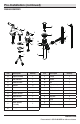
Pre-Installation (continued) PACKAGE CONTENTS V K B A T C L U D E G F M N S R Q H I P O J Part Quantity Part A Description Spout assembly 1 L Flange 1 B Hot end valve 1 M Gasket 1 C Cold end valve 1 N Nut 1 D Washer 2 O Pop-up body 1 E Nut 2 P Clip 1 F Screw 4 Q Horizontal rod 1 G Rubber washer 1 R Button 2 H Metal washer 1 S Slip joint 2 I Nut 1 J Quick connect assembly 1 K Stopper 1 3 Description Quantity T Strap 1 U Clip 1
Installation the hot and cold 1 Installing the spout assembly 2 Connecting valves CAUTION: Always turn off the water supply before removing an existing faucet or replacing any part of a faucet. Open the faucet handle to relieve water pressure and ensure that the water is completely shut off. □ □ □ NOTE: The hot side end valve is labeled. Shut off the water supply. Place the spout assembly (A) through the middle mounting hole in the sink.
Installation (continued) 3 Connecting the hose □ □ the waterline 4 Making connections Align the tabs (1 & 2) on the quick connect assembly (J). Push the quick connect assembly (J) firmly upward and snap it onto the receiving tube tab. Pull down moderately to ensure the connection has been made. NOTE: The hot side inlet tube is indicated by a label. If the label is not present, the hot supply tube is the longer of the two inlet tubes. □ Use 1/2 in. I.P.S.
Installation (continued) the pop-up body and 5 Preparing the pop-up assembly 6 Installing pop-up flange Remove the stopper (K) and flange (L). Screw the nut (N) all the way down, and push the gasket (M) down. □ Apply silicone to the underside of the flange (L). □ Insert the pop-up body (O) into the sink. Screw the flange (L) onto the pop-up body (O). The pivot hole (1) must face the back of the sink. □ Use the groove joint pliers to tighten the nut (N), but do not over tighten.
Installation (continued) the horizontal rod, Adjusting the length of 7 Installing 8 stopper, and strap horizontal rod □ □ Install the horizontal rod (Q) and stopper (K), as shown (1) and (2). Make sure the horizontal rod (P) insert into the pop-up body (O) completely, as shown (3). NOTE: If the horizontal rod of the pop-up assembly is too long, do not cut, it can be adjusted. Close the easy install rotating clip (P).
Installation (continued) 9 Installing the lift rod 10 Remove the quick connector □ Slide the lift rod (V) through the faucet assembly (A) until the knob rests on the faucet assembly. □ Push the pivot rod (Q) to the down position until the stopper (K) is completely open. Press the button (R) on the slip joint assembly (S) and adjust the vertical rod (T) up or down and front or back along the pivot rod (Q) until the vertical rod (T) is in the correct position to engage with the lift rod (V).
Operation 1 Flushing and checking for leaks IMPORTANT: After installation is complete, remove the aerator to flush the water lines. Do not lose the gasket (1) in the aerator. □ □ Turn on the water supply and allow both hot and cold water to run for at least one minute each. This flushes away any debris that could cause damage to internal parts. While the water is running, check for leaks. □ Turn off the water and replace the aerator.
Service Parts *Specify Finish 1 2 3 4 5 6 7 23 8 9 10 21 14 22 15 16 17 18 19 Part 1 Description Index 20 11 12 13 Part Number Part RP10057* 15 Washer Description Part Number RP64193 2 Screw RP50005 16 Nut RP56094 3 Handle seat RP17106* 17 Block RP70421 4 Handle RP13171* 18 O-ring RP60002 5 Inverter RP64044 6 Bonnet RP70435 19 Quick connect assembly RP70430 20 Easy install drain body RP40192* 21 Easy install drain assembly less body RP40193 22 Easy install
Questions, problems, missing parts? Before returning to the store, call Glacier Bay Customer Service 8 a.m. - 7 p.m., EST, Monday - Friday 9 a.m. - 6 p.m., EST, Saturday 1-855-HD-GLACIER (1-855-434-5224) HOMEDEPOT.COM Retain this manual for future use.
Modelo núm. 67575W-6001 67575W-6004 SKU núm. 703464 703460 GUÍA DE USO Y MANTENIMIENTO GRIFO PARA LAVAMANOS, DE DOS LLAVES ¿Problemas, preguntas o piezas faltantes? Antes de regresar a la tienda, llama al servicio al cliente de Glacier Bay de lunes a viernes entre 8 a.m. y 7 p.m. y los sábados entre 9 a.m. y 6 p.m.(hora estándar del Este) 1-855-HD-GLACIER (1-855-434-5224) HOMEDEPOT.COM GRACIAS Agradecemos la confianza que has depositado en Glacier Bay al comprar este grifo para lavamanos.
Tabla de contenido Información de seguridad ......................13 Garantía...................................................13 Pre-instalación .......................................13 Planificación de la instalación .............13 Herramientas necesarias ....................13 Contenido del paquete .........................14 Instalación ..............................................15 Funcionamiento ......................................20 Cuidado y limpieza ................................
Pre-instalación (continuación) CONTENIDO DEL PAQUETE V K B A T C L U D E G F M N S R Q H I P O J Pieza Descripción Cantidad Pieza Descripción Cantidad K Tapón 1 L Brida 1 M Junta 1 N Tuerca 1 O Cuerpo emergente 1 A Ensamblaje del caño 1 B Válvula de extremo para agua caliente 1 C Válvula de extremo para agua fría 1 D Arandela 2 P Sujetador 1 E Tuerca 2 Q Varilla horizontal 1 F Tornillo 4 R Botón 2 G Arandela de goma 1 S Alicate ajustable 2
Instalación instalar el ensamblaje conectar las válvulas de 1 Cómo 2 Cómo del caño agua fría y caliente PRECAUCIÓN: Cierra siempre el suministro de agua antes de quitar un grifo existente o reemplazar cualquier pieza de un grifo. Abre la llave del grifo para liberar la presión de agua y asegúrate de que el suministro de agua esté completamente cerrado. □ □ □ NOTA: La válvula de agua caliente está etiquetada. Cierra el suministro de agua.
Instalación (continuación) hacer las conexiones de 3 Cómo conectar la manguera 4 Cómo las tuberías de agua □ □ Alinea las pestañas (1 y 2) en el ensamblaje del conector rápido (J). Presiona firmemente el ensamblaje del conector rápido (J) hacia arriba hasta que encaje en la pestaña del tubo receptor. Hala hacia abajo ligeramente para asegurar que la conexión es segura. NOTA: El tubo de entrada del agua caliente se identifica con una etiqueta.
Instalación (continuación) preparar el ensamblaje instalar el cuerpo 5 Cómo 6 Cómo emergente emergente y la brida emergente Retira el tapón (K) y la brida (L). Enrosca la tuerca (N) hasta el límite. Presiona la junta (M) hacia abajo. □ Aplica silicona en el lado inferior de la brida (L). □ Inserta el cuerpo emergente (O) en el lavamanos. Enrosca la brida (L) en el cuerpo emergente (O). El orificio del pivote (1) debe mirar hacia la parte trasera del lavamanos.
Instalación (continuación) instalar la varilla Cómo ajustar el largo de la 7 Cómo horizontal, el tapón y la correa 8 varilla horizontal □ Instala la varilla horizontal (Q) y el tapón (K) tal como se muestra en (1) y (2). Asegúrate de que la varilla horizontal (Q) se inserte completamente en el cuerpo emergente (O), como se muestra en (3) . □ Cierra el sujetador giratorio fácil de instalar (P).
Instalación (continuación) instalar la varilla de 9 Cómo elevación 10 Quita el conector rápido □ □ Desliza la varilla de elevación (V) a través del ensamblaje del grifo (A) hasta que la perilla esté apoyada sobre este. □ Empuja la varilla pivotante (Q) hacia abajo hasta que el tapón (K) esté completamente abierto.
Funcionamiento 1 Cómo purgar las tuberías y comprobar que no haya fugas IMPORTANTE: Después de terminar la instalación, retira el aireador para purgar las tuberías de agua. No aflojes la junta (1) en el aireador. □ Abre el suministro de agua y deja correr agua fría y caliente durante al menos un minuto cada una. Esto enjuagará cualquier suciedad que podría dañar las piezas internas. □ Con el chorro abierto, verifica que no haya fugas. □ Cierra el suministro de agua y vuelve a colocar el aireador.
Piezas de repuesto *Especificar acabado 1 2 3 4 5 6 7 23 8 9 10 21 14 22 15 16 17 18 19 Pieza Descripción 20 11 12 13 Numéro de pièce Pieza 1 Índice RP10057* 16 Tuerca RP56094 2 Tornillo RP50005 17 Bloque RP70421 3 Asiento de la llave RP17106* 18 Aro tórico RP60002 4 Llave RP13171* 5 Invertidor RP64044 19 Ensamblaje del conector rápido RP70430 20 Cuerpo del desagüe fácil de instalar RP40192* 6 Bonete RP70435 7 Cartucho (H) RP20035 8 Cartucho (C) RP20036 9
¿Problemas, preguntas o piezas faltantes? Antes de regresar a la tienda, llama al servicio al cliente de Glacier Bay de lunes a viernes entre 8 a.m. y 7 p.m. y los sábados entre 9 a.m. y 6 p.m.(hora estándar del Este) 1-855-HD-GLACIER (1-855-434-5224) HOMEDEPOT.COM Conserva este manual para uso futuro.
Modèle n° 67575W-6001 67575W-6004 UGS n° 703464 703460 GUIDE D’INSTALLATION ET D’ENTRETIEN ROBINET DE LAVABO À DEUX MANETTES Questions, problèmes, pièces manquantes? Avant de retourner au magasin, appelez le service à la clientèle Glacier Bay entre 8 h et 19 h, HNE, du lundi au vendredi au entre 9 h et 18 h, HNE, le samedi au 1-855-HD-GLACIER (1-855-434-5224) HOMEDEPOT.COM THANK YOU Nous vous remercions d'avoir fait confiance à Glacier Bay en achetant ce robinet de salle de bains.
Table des matières Consignes de sécurité ............................24 Garantie...................................................24 Pré-installation .......................................24 ................24 Outils requis .........................................24 Contenu de l’emballage .......................25 Installation ..............................................26 Utilisation ................................................31 Entretien et nettoyage ............................
Pré-installation (suite) CONTENU DE L'EMBALLAGE V K B A T C L U D E G M N F S R Q H I P O J Pièce Description Quantité Pièce K Bonde 1 L Bride 1 M Joint d'étanchéité 1 N Écrou 1 O Corps d'évacuation mécanique 1 A Bec du robinet 1 B Robinet d'arrêt d'eau chaude 1 Description Quantité C Robinet d'arrêt d'eau froide 1 D Rondelle 2 E Écrou 2 P Attache 1 F Vis 4 Q Tige horizontale 1 G Rondelle en caoutchouc 1 R Bouton 2 S Joint coulissant 2 H R
Installation des robinets 1 Installation du bec du robinet 2 Branchement d'arrêt d'eau chaude et froide ATTENTION : Coupez l’alimentation en eau CAUTION: Always turntoujours off the water supply before avant d’enlever un robinet ou de any remplacer removing an existing faucetexistant or replacing part of a n’importe quelle partie du robinet. Ouvrez la poignée du faucet.
Installation (suite) 3 Raccord du tuyau flexible □ □ des conduites 4 Branchement d'alimentation en eau Alignez les languettes (1et 2) sur le raccord à branchement rapide (J). Poussez fermement le raccord à branchement rapide (J) vers le haut et enclenchez-le sur la languette du tuyau récepteur. Tirez modérément vers le bas pour vous assurer que le branchement est bien fait. REMARQUE : Le tuyau d'arrivée de l'eau chaude est indiqué par une étiquette.
Installation (suite) Préparation de l'évacuation mécanique. □ Retirez la bonde (K) et la bride (L). □ Vissez l'écrou (N) entièrement. Glissez le joint (M) vers le bas. du corps et de la 6 Installation bride d'évacuation mécanique □ Appliquez de la silicone sur le dessous de la bride (L). □ Insérez le corps d'évacuation mécanique (O) dans le lavabo. Vissez la bride (L) sur le corps d'évacuation mécanique (O). Le trou de pivot (1) doit être orienté vers l'arrière du lavabo.
Installation (suite) 7 □ □ Installation de la tige horizontale, de la bonde et de la courroie la longueur de la tige 8 Régler horizontale REMARQUE : Si la tige horizontale de l’évacuation mécanique est trop longue, ne la coupez pas, elle peut être ajustée. Installez la tige horizontale (Q) et la bonde (K) comme illustré (1) et (2). Assurez-vous que la tige horizontale (Q) est insérée complètement dans le corps d’évacuation mécanique (O) comme illustré (3).
Installation (suite) le raccord à 9 Installation de la tige de levage 10 Retirez branchement rapide □ □ Faites glisser la tige de levage (V) dans le robinet (A) jusqu’à ce que le bouton repose sur le robinet. □ Poussez la tige du pivot (Q) vers le bas jusqu’à ce que la bonde (K) soit complètement ouverte.
Utilisation 1 Purge et recherche de fuites IMPORTANT : Une fois l’installation terminée, retirez l’aérateur pour purger les conduites d'alimentation en eau. Ne perdez pas le joint d’étanchéité (1) dans l’aérateur. □ Ouvrez l'alimentation en eau et laissez couler l'eau chaude et l'eau froide au moins une minute chacune. Ceci purge tous les débris qui pourraient endommager les pièces internes. □ Pendant que l’eau coule, vérifiez s’il y a des fuites.
Pièces de rechange *Spécifiez un fini 1 2 3 4 5 6 7 23 8 9 10 21 14 22 15 16 17 18 19 Pièce Description 20 11 12 13 Numéro de pièce Pièce 1 Indicateur RP10057* 15 Rondelle RP64193 2 Vis RP50005 16 Écrou RP56094 3 Base de la poignée RP17106* 17 Bloc RP70421 4 Manette RP13171* 18 Joint torique RP60002 5 Inverseur RP64044 6 Chapeau RP70435 19 Raccord à branchement rapide RP70430 7 Cartouche (H) RP20035 8 Cartouche (C) RP20036 20 Corps d’évacuation facile à in
Questions, problèmes, pièces manquantes? Avant de retourner au magasin, appelez le service à la clientèle Glacier Bay entre 8 h et 19 h, HNE, du lundi au vendredi au entre 9 h et 18 h, HNE, le samedi au 1-855-HD-GLACIER (1-855-434-5224) HOMEDEPOT.COM Conservez ce manuel pour référence future.