Model# 873X-0804 873X-0827D HD873X-0801 HD873X-0802 873X-0904 HD873X-0901 HD873X-0927D SKU# 1001818631 1001819058 301879838 301879834 1001819034 301879836 301879832 INSTALLATION AND CARE GUIDE SINGLE-HANDLE TUB AND SHOWER FAUCET Questions, problems, missing parts? Before returning to the store, call Glacier Bay Customer Service 8 a.m. - 7 p.m., EST, Monday - Friday 9 a.m. - 6 p.m., EST, Saturday 1-855-HD-GLACIER (1-855-434-5224) HOMEDEPOT.
Table of Contents Important Information ..............................2 Warranty ...................................................2 Pre-Installation .........................................3 Planning Installation ..............................3 Tools and Hardware Required ...............3 Package Contents ..................................6 Installation ................................................7 Care and Cleaning ....................................14 Troubleshooting .............................
Pre-Installation PLANNING INSTALLATION ADVANCED INSTALLATION: Consult a plumber or professional before installing this product. Before beginning the installation of this product, ensure all parts are present. Compare parts with the Package Contents list. If any part is missing or damaged, do not attempt to install the product. Contact Customer Service for replacement parts. All installations can vary depending on how your previous faucet was installed.
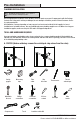
Pre-Installation (continued) B. IPS Measuring tape Tube cutter Key hole saw Adjustable wrench Phillips screwdriver Flathead screwdriver Silicone sealant Thermometer Thread sealant tape Flashlight Strap wrench Pipe wrench SI LI CO NE Safety goggles C.
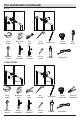
Pre-Installation (continued) D. CPVC+COPPER COPPER Measuring tape Tube cutter Key hole saw Thermometer Thread sealant tape Flashlight LI CO NE Safety goggles COPPER SI P i pe J o in t C o m p ou n d Adjustable wrench Phillips screwdriver Flathead screwdriver Silicone sealant 5 Strap wrench CPVC cement P i pe J o in t C o m p ou n d CPVC cleaner HOMEDEPOT.COM/GLACIERBAY Please contact 1-855-HD-GLACIER for further assistance.
Pre-Installation (continued) PACKAGE CONTENTS A B C D E I F M J G H O N L K Part Description Quantity A Shower flange 1 B Shower arm 1 C Shower head 1 D Valve body 1 E Escutcheon 1 F Handle 1 G Set screw 1 H 2.5mm hex wrench 1 I Plug 1 J Tub spout 1 K Screw 2 L Plaster guard 1 M Escutcheon screw 2 N Index 1 O 3.
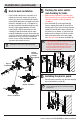
Installation 1 Preparing for installation the valve body and 2 Installing removing the plaster guard CAUTION: Always shut off the water supply before removing an existing faucet or replacing any part of a faucet. Open the faucet handle to relieve water pressure and ensure that the water is completely shut off. □ Shut off the water supply to the tub and shower.
Installation (continued) the supply 3a Installing connections the supply 3b Installing connections (for soldering) NOTE: The hot water supply lines go into the "H" inlet, and the cold water supply lines go into the "C" inlet. Do not use PEX or CPVC between the valve body (D) and tub spout (J). NOTE: The hot water supply lines go into the "H" inlet, and the cold water supply lines go into the "C" inlet. Do not use PEX or CPVC between the valve body (D) and tub spout (J).
Installation (continued) 4 Back to back installation □ the water outlets 5 Flushing and checking for leaks □ If the hot and cold inlets are reversed (hot on right and cold on left), remove the screw (1), inverter (2), sleeve (3), and bonnet (4) from the valve body (D) with reversed supply connections. Rotate the cartridge (5) 180°, so H appears on the right. Install the cartridge making sure that the key is fully engaged with the slot in the valve body (D).
Installation (continued) 7 Installing the shower arm 8 Installing the tub spout □ Insert the long end of the shower arm (B) through the shower flange (A), and wrap thread sealant tape (not included) around the long end of the shower arm (B) in a clockwise direction, as shown. □ Install the long end of the shower arm (B) into the pipe elbow inside the wall. Carefully tighten the shower arm (B) with a clean strap wrench. Do not over tighten.
Installation (continued) 9 Removing the plastic cap □ 10 Adjusting the temperature NOTE: The limiter on the valve can be set to allow partial or full access to hot water by limiting how far the handle can be turned to the hot side of the valve. The limiter is typically set at the factory to allow only warm water to pass through the valve. Follow the directions in this section if you wish to adjust the amount of hot water that is allowed through the valve.
Installation (continued) 10 Adjusting the temperature B Removing the red limit stop ring □ Remember the position of the red limit stop ring (1) on the cartridge assembly (2). Remove the red limit stop ring (1) from the cartridge assembly (2). 1 2 C Adjusting the desired maximum water temperature □ For colder water, adjust the red limit stop ring (1) in a clockwise direction and reinstall the red limit stop ring (1) onto the cartridge assembly (2).
Installation (continued) 10 Adjusting the temperature Reinstalling the inverter and D sleeve D NOTE: Rotate the cartridge stem (1) clockwise to turn off the water before you install the handle. □ □ Place the inverter (2) onto the valve body (D) and rotate the inverter (2) with the arrow side facing down. Then secure with the screw (3). 2 3 4 1 Screw the sleeve (4) onto the valve body (D).
Installation (continued) 12 Checking for leaks □ Turn the handle (F) to the full on mixed position. □ When the valve body (D) is turned on, water normally flows through the tub spout (J). To activate the shower, turn the valve on and pull the knob (1) up. Hold the knob (1) until the water flows continuously from the shower arm (B). Check for leaks. □ B Shut off the water at the faucet and supply lines.
Troubleshooting NOTE: Refer to the Service Parts section in this manual for a detailed drawing showing the location of the parts listed below. Problem Possible Cause There is no hot water. □ The lines are reversed or the cartridge is installed upside down. □ Rotate the cartridge 180°. □ The balance valve in cartridge is clogged with debris. □ Clean the bottom of the cartridge. □ One or both water supplies are not turned on. □ Turn both water supply valves to the on position.
Service Parts 1 2 3 5 4 6 7 8 11 16 9 Faucet ID tags can be found by removing the handle 10 12 17 13 14 15 Part 1 Part Number Part Shower flange RP38046* 10 Description Description Part Number Screw RP70560 2 Shower arm RP38047* 11 Escutcheon RP80554* 3 Shower head RP38306* 12 Escutcheon screw RP50190* 4 O-ring RP60101 13 Handle RP13469* 5 Cartridge RP20075 14 Set screw RP50002 RP7043701 15 Index RP10055 6 Bonnet nut 7 O-ring RP60091 16 Plug RP7036
Questions, problems, missing parts? Before returning to the store, call Glacier Bay Customer Service 8 a.m. - 7 p.m., EST, Monday - Friday 9 a.m. - 6 p.m., EST, Saturday 1-855-HD-GLACIER (1-855-434-5224) HOMEDEPOT.COM/GLACIERBAY Retain this manual for future use.
Modelo núm. 873X-0804 873X-0827D HD873X-0801 HD873X-0802 873X-0904 HD873X-0901 HD873X-0927D SKU núm. 1001818631 1001819058 301879838 301879834 1001819034 301879836 301879832 GUÍA DE USO Y MANTENIMIENTO GRIFO PARA BAÑERA Y DUCHA, DE UNA SOLA LLAVE ¿Problemas, preguntas o piezas faltantes? Antes de regresar a la tienda, llama al servicio al cliente de Glacier Bay de lunes a viernes entre 8 a.m. y 7 p.m. y los sábados entre 9 a.m. y 6 p.m.
Tabla de contenido Información importante .........................19 Garantía...................................................19 Pre-instalación .......................................20 Planificación de la instalación .............20 Herramientas y herrajes necesarios ....20 Contenido del paquete .........................23 Instalación ..............................................24 Cuidado y limpieza ................................31 Solución de problemas ...........................
Pre-instalación PLANIFICACIÓN DE LA INSTALACIÓN INSTALACIÓN AVANZADA: Consulta a un plomero o profesional antes de instalar este producto. Antes de comenzar la instalación de este producto, asegúrate de que no falta ninguna pieza. Compara las piezas con la lista de Contenido del paquete. Si falta alguna pieza o está dañada, no intentes instalar el producto. Comunícate con el servicio al cliente para piezas de repuesto.
Pre-instalación (continuación) B. IPS Gafas de seguridad Cortador de tuberías Serrucho de punta Termómetro Cinta selladora para roscas Linterna Llave de correa Llave para tubería SI LI CO NE Cinta métrica Llave ajustable Destornillador Destornillador de Phillips cabeza plana Sellador de silicona C.
Pre-instalación (continuación) D. CPVC+COBRE COBRE Cinta métrica Cortador de tuberías Serrucho de punta Termómetro Cinta selladora para roscas Linterna LI CO NE Gafas de seguridad COBRE SI P i pe J o in t C o m p ou n d Llave ajustable Destornillador Destornillador de Phillips cabeza plana Sellador de silicona 22 Llave de correa Cemento CPVC P i pe J o in t C o m p ou n d Limpiador CPVC HOMEDEPOT.COM/GLACIERBAY Para obtener asistencia, llama al 1-855-HD-GLACIER.
Pre-instalación (continuación) CONTENIDO DEL PAQUETE A B C D E I F M J G H O N L K Pieza Descripción Cantidad A Brida de la ducha 1 B Brazo de la ducha 1 C Cabezal de la ducha 1 D Cuerpo de la válvula 1 E Placa protectora 1 F Llave 1 G Tornillo de fijación 1 H Llave hexagonal de 2.5 mm 1 I Tapón 1 J Caño de la bañera 1 K Tornillo 2 L Protector de yeso 1 M Tornillo de la placa protectora 2 N Índice 1 O Llave hexagonal de 3.
Instalación 1 2 Cómo prepararse para la instalación PRECAUCIÓN: Cierra siempre el suministro de agua antes de retirar un grifo existente o reemplazar alguna parte del mismo. Abre la llave del grifo para liberar la presión de agua y asegúrate de que el suministro de agua esté completamente cerrado. □ □ □ El protector de yeso (L) se coloca de forma tal que esté al ras con la pared acabada. Esto garantiza que la válvula estará en la posición correcta para aceptar el regulador.
Instalación (continuación) instalar las conexiones instalar las conexiones 3a Cómo 3b Cómo de suministro de suministro (para soldar) NOTA: Las líneas de suministro de agua caliente van en la entrada “H” y las de agua fría, en la entrada “C”. No uses PEX ni CPVC entre el cuerpo de la válvula (D) y el caño de la bañera (J). NOTA: Las líneas de suministro de agua caliente van en la entrada “H” y las de agua fría, en la entrada “C”.
Instalación (continuación) 4 □ 5 Instalación de parte posterior con posterior Si las entradas de agua caliente y fría se revierten (caliente a la derecha y fría a la izquierda), quita el tornillo (1), el inversor (2), la funda (3) y el bonete (4) del cuerpo de la válvula (D) con conexiones de suministro revertidas. Rota el cartucho (5) 180° de forma tal que H aparezca en la derecha. Instala el cartucho asegurándote de que la llave esté bien enganchada con la ranura en el cuerpo de la válvula (D).
Instalación (continuación) instalar el brazo de la instalar el caño de la 7 Cómo 8 Cómo ducha bañera □ Inserta el extremo largo del brazo de la ducha (B) a través de la brida de esta (A) y coloca cinta selladora para rosca (no incluida) alrededor de aquel (B), en el sentido de las manecillas del reloj, tal como se muestra. □ Coloca el extremo largo del brazo de la ducha dentro del codo de tubería que está dentro de la pared. Aprieta con cuidado el brazo de la ducha con una llave de correa limpia.
Instalación (continuación) 9 Cómo quitar la tapa de plástico 10 Cómo ajustar la temperatura □ NOTA: El limitador de la válvula puede configurarse para permitir acceso parcial o total al agua caliente al limitar hasta dónde puede girarse la manija en el lado del agua caliente de la válvula. El limitador usualmente está configurado de fábrica para permitir sólo el paso de agua tibia a través de la válvula.
Instalación (continuación) 10 Cómo ajustar la temperatura quitar el aro de retención B Cómo de límite rojo □ Recuerda la posición del aro de retención del límite rojo (1) en el conjunto del cartucho (2). Quita el aro del tope de límite rojo (1) del ensamblaje del cartucho (2). 1 2 ajustar la deseada C Cómo temperatura máxima del agua □ Para agua más fría, ajusta el aro de retención del límite rojo (1) hacia la derecha y vuelve a instalarlo (1) en el conjunto del cartucho (2).
Instalación (continuación) 10 Cómo ajustar la temperatura Cómo reinstalar el inversor y D la funda D NOTA: Rota el vástago del cartucho (1) hacia la derecha para cortar el suministro de agua antes de instalar la manija. □ □ Coloca el inversor (2) en el cuerpo de la válvula (D) y gíralo (2) con el lado de la flecha mirando hacia abajo. Enseguida asegura con el tornillo (3). Enrosca la funda (4) en el cuerpo de la válvula (D).
Instalación (continuación) comprobar que no 12 Cómo haya fugas □ Gira la manija (F) por completo hacia la posición de mezclado. □ Cuando el cuerpo de la válvula (D) está abierto, el agua sale normalmente por el caño de la bañera (J). Para activar la ducha, abre la válvula y hala la perilla (1) hacia arriba. Sostén la perilla (1) hasta que el agua corra de forma continua desde el brazo de la ducha (B). Verifica que no haya filtraciones.
Solución de problemas NOTA: Consulta en la sección de piezas de repuesto de este manual una ilustración detallada sobre la ubicación de las piezas enumeradas más abajo. Problema Posible causa No hay agua caliente. □ □ No hay flujo de agua o es insuficiente. Hay una fuga o filtración desde el caño cuando la manija está cerrada. Solución Las líneas están revertidas o el cartucho □ está instalado hacia abajo. La válvula compensadora dentro del □ cartucho está obstruida por residuos.
Piezas de repuesto 1 2 3 5 4 6 7 8 11 16 9 10 Las etiquetas de identificación del grifo pueden encontrarse al retirar la llave.
¿Problemas, preguntas o piezas faltantes? Antes de regresar a la tienda, llama al servicio al cliente de Glacier Bay de lunes a viernes entre 8 a.m. y 7 p.m. y los sábados entre 9 a.m. y 6 p.m.(hora estándar del Este) 1-855-HD-GLACIER (1-855-434-5224) HOMEDEPOT.COM/GLACIERBAY Conserva este manual para uso futuro.