Internet# 304685565 304685874 Model# HD67109W-8004 HD67109W-8096H SKU# 1003141960 1003141962 INSTALLATION AND CARE GUIDE SINGLE-HANDLE LAVATORY FAUCET Questions, problems, missing parts? Before returning to the store, call Glacier Bay Customer Service 8 a.m. - 7 p.m., EST, Monday - Friday 9 a.m. - 6 p.m., EST, Saturday 1-855-HD-GLACIER (1-855-434-5224) HOMEDEPOT.COM THANK YOU We appreciate the trust and confidence you have placed in Glacier Bay through the purchase of this lavatory faucet.
Table of Contents Important Information ..............................2 Warranty ...................................................2 Pre-Installation .........................................2 Planning Installation ..............................2 Tools and Hardware Required ...............2 Package Contents ..................................3 Installation ................................................4 Operation...................................................8 Care and Cleaning ......................
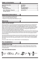
Pre-Installation (continued) PACKAGE CONTENTS Faucet Assembly ClickInstall Drain Assembly Q H* A O I* P G E F R J* K* N M S L* B T C D NOTE: *Items H - L come pre-assembled.
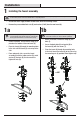
Installation 1 Installing the faucet assembly CAUTION: Always shut off the water supply before removing an existing faucet or replacing any part of a faucet. Open the faucet handle to relieve water pressure and ensure that the water is completely shut off. □ Shut off the water supply. Remove the old faucet. Clean the mounting surface. □ Remove the preassembled lock nuts (D) and washers (B & C) from the new faucet (A). 1a 1b NOTE: This step is for flange installation (optional).
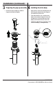
Installation (continued) 3 Preparing the pop-up assembly 4 Installing the drain body Remove the pop-up stopper (H) and drain flange (I) from the drain body (L). H □ Apply silicone sealant (not included) under the drain flange (I) and place the drain flange (I) into the drain hole of the sink. □ From underneath the sink, screw the drain body (L) onto the drain flange (I). Ensure that the opening (1) for the ball rod on the drain body (L) faces towards the rear of the sink.
Installation (continued) the stopper and 5 Installing horizontal rod □ Before installation, unscrew the protective cap (1) from the horizontal rod (N). □ Insert the stopper (H) into the drain hole in the sink. Insert the horizontal rod (N) into the drain body (L) and through the hole of the stopper (H) until you hear a click. See insert 2. You can press the two sides of the joint (M) to remove the horizontal rod (N).
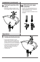
Installation (continued) 7 Attaching the horizontal rod and strap □ Press the horizontal rod (N) down to ensure the stopper (H) is in the maximum open position. □ Slide the clip (P) upward, adjust the location of the lift rod strap (O) to the appropriate height and insert the horizontal rod (N) with the correct hole of the lift rod strap (O). □ Move the lift rod strap (O) in or out to choose an appropriate location. □ Slide the clip (P) downward until it secures with the horizontal rod (N).
Installation (continued) the operation of the the water supply 9 Checking pop-up 10 Making connections □ Operate the lift rod (Q) up and down to verify that the stopper (H) opens and closes correctly. □ Use 1/2 in. I.P.S. faucet connections (2), or use supply line coupling nuts (3) (not included) with a 3/8 in. O.D. ball-nose riser (1). □ Use wrenches to tighten the connections. Do not overtighten.
Care and Cleaning □ To clean, wipe down with a damp cloth and dry with a towel. □ Do not use abrasive cleaners, steel wool, or harsh chemicals when cleaning this faucet, or the warranty will be voided. Troubleshooting NOTE: Refer to the service parts section in this manual for a detailed drawing showing the location of the parts listed below. Problem Possible Cause There are leaks from the handle. The bonnet nut has come loose and/or the washer is dirty or damaged. □ Tighten the bonnet nut.
Service Parts 1 2 16 3 4 9 5 6 10 7 11 15 12 8 Faucet ID tags can be found on the hot water inlet Part Description 13 14 Part Number Part 1 Handle assembly RP13604* 10 Bolt RP50023 2 Cap RP80028* 11 Rubber washer RP64008 3 Bonnet nut RP70010 12 Metal washer RP64009 4 Cartridge RP20005 13 Lock nut RP56005 5 Deck plate RP80005* 14 Screen filter RP70072 6 Gasket RP70011 7 Mounting nut RP56001 15 ClickInstall™ drain assembly RP40228* 8 Screw RP50007 16
Questions, problems, missing parts? Before returning to the store, call Glacier Bay Customer Service 8 a.m. - 7 p.m., EST, Monday - Friday 9 a.m. - 6 p.m., EST, Saturday 1-855-HD-GLACIER (1-855-434-5224) HOMEDEPOT.COM Retain this manual for future use.
Internet núm. Modelo núm. 304685565 HD67109W-8004 304685874 HD67109W-8096H SKU núm. 1003141960 1003141962 GUÍA DE USO Y MANTENIMIENTO GRIFO PARA LAVAMANOS, DE UNA SOLA LLAVE ¿Problemas, preguntas o piezas faltantes? Antes de regresar a la tienda, llama al servicio al cliente de Glacier Bay de lunes a viernes entre 8 a.m. y 7 p.m. y los sábados entre 9 a.m. y 6 p.m.(hora estándar del Este) 1-855-HD-GLACIER (1-855-434-5224) HOMEDEPOT.
Tabla de contenido Información importante .........................13 Garantía...................................................13 Pre-instalación .......................................13 Planificación de la instalación .............13 Herramientas y herrajes necesarios ....13 Contenido del paquete .........................14 Instalación ..............................................15 Funcionamiento ......................................19 Cuidado y limpieza ................................
Pre-instalación (continuación) CONTENIDO DEL PAQUETE Ensamblaje de la mezcladora Ensamblaje de desagüe ClickInstall Q H* A O I* P G E F R J* K* N M S L* B T C NOTA: *Los artículos H - L vienen preensamblados.
Instalación 1 Cómo instalar el ensamblaje del grifo PRECAUCIÓN: Cierra siempre el suministro de agua antes de retirar un grifo existente o reemplazar alguna parte del mismo. Abre la llave del grifo para liberar la presión de agua y asegúrate de que el suministro de agua esté completamente cerrado. □ Cierra el suministro de agua. Retira el grifo anterior. Limpia la superficie de montaje. □ Retira las contratuercas (D) preensambladas y las arandelas (B y C) del grifo (A) nuevo.
Instalación (continuación) preparar el ensamblaje instalar el cuerpo del 3 Cómo 4 Cómo emergente drenaje Retira el tapón emergente (H) y la brida del desagüe (I) del cuerpo del desagüe (L). H □ Aplica sellador de silicona (no incluido) debajo de la brida del drenaje (I) y coloca ésta dentro del orificio de drenaje del lavabo. □ Desde la parte inferior del lavabo, enrosca el cuerpo del drenaje (L) en la brida del drenaje (I).
Instalación (continuación) instalar el tapón y la 5 Cómo varilla horizontal instalar la varilla de 6 Cómo elevación □ □ Antes de la instalación, desenrosca la tapa protectora (1) de la varilla horizontal (N). □ Inserta el tapón (H) en el orificio del drenaje del lavabo. Inserta la varilla horizontal (N) en el cuerpo del desagüe (L) y a través del orificio del tapón (H) hasta que escuches un clic. Consulta el folleto 2. Puedes presionar ambos lados de la junta (M) para retirar la varilla horizontal (N).
Instalación (continuación) 7 Cómo instalar la varilla horizontal y la correa □ Presiona hacia abajo la varilla horizontal (N) para garantizar que el tapón (H) esté abierto completamente. □ Desliza la presilla (P) hacia arriba, ajusta la ubicación de la correa de la varilla de elevación (O) a la altura adecuada e inserta la varilla horizontal (N) con el orificio correcto de la varilla de elevación (O).
Instalación (continuación) 9 □ Cómo verificar el funcionamiento del tapón emergente hacer las conexiones 10 Cómo del suministro de agua □ Usa conexiones de grifos de 1/2" IPS (2) o tuercas de acoplamiento de líneas de suministro (3) (no incluidas) con un tubo montante de bola de diámetro exterior de 3/8" (1). □ Usa llaves para apretar las conexiones. No aprietes demasiado. Mueve la varilla de elevación (Q) hacia arriba y abajo para verificar que el tapón (H) se abre y cierra correctamente.
Cuidado y limpieza □ Para limpiar, usa un paño húmedo y seca con una toalla. □ No uses limpiadores abrasivos, esponjas de alambre o productos químicos fuertes para limpiar esta mezcladora, pues ello anulará la garantía. Solución de problemas NOTA: Consulta la sección de piezas de repuesto de este manual para ver un dibujo detallado que muestra la ubicación de las piezas enumeradas a continuación. Problema Posible causa Hay filtración por el maneral.
Piezas de repuesto 1 2 16 3 4 9 5 6 10 7 11 15 12 8 Las etiquetas de identificación de la mezcladora pueden encontrarse en la entrada de agua caliente.
¿Problemas, preguntas o piezas faltantes? Antes de regresar a la tienda, llama al servicio al cliente de Glacier Bay de lunes a viernes entre 8 a.m. y 7 p.m. y los sábados entre 9 a.m. y 6 p.m.(hora estándar del Este) 1-855-HD-GLACIER (1-855-434-5224) HOMEDEPOT.COM Conserva este manual para uso futuro.
Internet nº 304685565 304685874 Modèle n° HD67109W-8004 HD67109W-8096H UGS n° 1003141960 1003141962 GUIDE D’INSTALLATION ET D’ENTRETIEN ROBINET DE LAVABO À UNE SEULE MANETTE Questions, problèmes, pièces manquantes? Avant de retourner au magasin, appelez le service à la clientèle Glacier Bay entre 8 h et 19 h, HNE, du lundi au vendredi au entre 9 h et 18 h, HNE, le samedi au 1-855-HD-GLACIER (1-855-434-5224) HOMEDEPOT.
Table des matières Information importante ..........................24 Garantie...................................................24 Pré-installation .......................................24 ................24 Outils et quincaillerie requis ................24 Contenu de l’emballage .......................25 Installation ..............................................26 Utilisation ................................................30 Entretien et nettoyage ............................31 Dépannage ............
Pré-installation (suite) CONTENU DE L'EMBALLAGE Robinet Évacuation ClickInstall Q H* A O I* G E P F R J* K* N M S L* B T C REMARQUE : *Les articles H à L sont fournis pré-assemblés.
Installation de l'ensemble de 1 Installation robinetterie ATTENTION : Fermez toujours l’alimentation en eau avant de retirer un robinet existant ou d’en remplacer une pièce quelconque. Ouvrez la poignée du robinet pour libérer la pression de l’eau et vous assurer que l’alimentation en eau est complètement coupée. □ Fermez l'alimentation en eau. Enlevez l’ancien robinet. Nettoyez la surface de montage. □ Retirez les contre-écrous (D) et rondelles (B et C) pré-assemblés du nouveau robinet (A).
Installation (suite) de l'évacuation du corps 3 Préparation 4 Installation mécanique d'évacuation Retirez la bonde de l’évacuation mécanique (H) et la bride d’évacuation (I) du corps d’évacuation (L). H □ Appliquez du mastic à la silicone (non compris) sous la bride d’évacuation (I) et placez la bride d’évacuation (I) dans le trou d’évacuation de l’évier. □ À partir du dessous de l’évier, vissez le corps d’évacuation (L) sur la bride d’évacuation (I).
Installation (suite) de la bonde et de 5 Installation 6 Installation de la tige de levage la tige horizontale □ Avant l’installation, dévissez le capuchon de protection (1) de la tige horizontale (N). □ Enfoncez la bonde (H) dans le trou d’évacuation de l’évier. □ Insérez la tige horizontale (N) dans le corps d’évacuation (L) et dans le trou de la bonde (H) jusqu’à ce que vous entendiez un déclic. Reportez-vous aux encarts 2.
Installation (suite) 7 Fixation de la tige horizontale et la courroie □ □ Poussez la tige horizontale (N) vers le bas pour assurer que la bonde (H) est dans la position ouverte maximale. Faites glisser la pince (P) vers le haut, réglez l’emplacement de la courroie de la tige de levage (O) à la hauteur appropriée, puis insérez la tige horizontale (N) dans le trou correct de la sangle de la tige de levage (O).
Installation (suite) 9 □ des conduites 10 Raccordement d’alimentation en eau Vérification du fonctionnement de l’évacuation mécanique Déplacez la tige de levage (Q) de haut en bas pour vérifier que la bonde (H) s’ouvre et se ferme correctement. Q □ Utilisez des raccords de robinet IPS de 1,27 cm (½ po) (2), ou utilisez des écrous d'accouplement pour conduite d'alimentation (3) (non compris) avec une colonne montante à bout sphérique de D.E. 9,53 mm (3/8 po) (1).
Entretien et nettoyage □ Pour nettoyer, essuyez avec un linge humide et séchez avec une serviette. □ N'utilisez pas de nettoyants abrasifs, de la laine d’acier ou de produits chimiques abrasifs pour nettoyer ce robinet, sinon la garantie sera annulée. Dépannage REMARQUE : Consultez la section pièces de rechange de ce guide pour une illustration détaillée de l’emplacement des pièces énumérées ci-dessous. Problème Cause possible La manette fuit.
Pièces de rechange 1 2 16 3 4 9 5 6 10 7 11 15 12 8 13 Les étiquettes d’identité du robinet se trouvent sur l’arrivée d’eau chaude Pièce Description 14 Numéro de pièce Pièce 1 Manette RP13604* 10 Boulon RP50023 2 Capuchon RP80028* 3 Écrou de chapeau RP70010 11 Rondelle en caoutchouc RP64008 4 Cartouche RP20005 12 Rondelle en métal RP64009 5 Plaque décorative RP80005* 13 Contre-écrou RP56005 14 Filtre à tamis RP70072 15 Ensemble d’évacuation ClickInstall™ RP
Questions, problèmes, pièces manquantes? Avant de retourner au magasin, appelez le service à la clientèle Glacier Bay entre 8 h et 19 h, HNE, du lundi au vendredi au entre 9 h et 18 h, HNE, le samedi au 1-855-HD-GLACIER (1-855-434-5224) HOMEDEPOT.COM Conservez ce manuel pour référence future.