Model# HD67495-1008D2 HD67495-1001 HD67495-1027D SKU# 1003291327 305514647 305514641 INSTALLATION AND CARE GUIDE NOTTELY TOUCHLESS SINGLE-HANDLE PULL-DOWN KITCHEN FAUCET Questions, problems, missing parts? Before returning to the store, call Glacier Bay Customer Service 8 a.m. - 7 p.m., EST, Monday - Friday 9 a.m. - 6 p.m., EST, Saturday 1-855-HD-GLACIER (1-855-434-5224) HOMEDEPOT.
Table of Contents Important Information ..............................2 Warranty ...................................................2 Pre-Installation .........................................2 Planning Installation ..............................2 Tools and Hardware Required ...............2 Package Contents ..................................3 Installation ................................................4 Operation ..................................................12 Care and Cleaning .....................
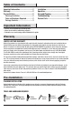
Pre-Installation (continued) PACKAGE CONTENTS Sensor Control Box A H C B D I E F G + J Part Description Quantity A Faucet body 1 B FastMount™ 1 C Escutcheon 1 D Gasket E Weight F Weight clip 1 Part - - + + - + Description Quantity G Quick connect assembly 1 H Sensor control box 1 1 I Battery pack 1 1 J "AA" Battery 4 3 HOMEDEPOT.COM/GLACIERBAY Please contact 1-855-HD-GLACIER for further assistance.
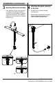
Installation 1 Preparing for installation CAUTION: Always shut off the water supply before removing an existing faucet or replacing any part of a faucet. Open the faucet handle to relieve water pressure and ensure that the water is completely shut off. □ Shut off the water supply. Remove the old faucet. Clean the mounting surface. □ Before installation, remove the quick connector (G) from the free end of the hose by unscrewing it in a counterclockwise direction.
Installation (continued) the quick connector 3 Securing the faucet assembly 4 Attaching to the hose □ From underneath the sink, secure the faucet assembly to the sink with the FastMount™ system (B). Push the FastMount™ system (B) up over the threads until it stops against the bottom of the sink, then hand turn (clockwise) to tighten (Fig 1). □ Pull out the hose (1) from the threaded mounting shank.
Installation (continued) 5 Installing the sensor cable NOTE: The side of the control box (H) with "in" and "out" showing must face the front of the cabinet (away from the back of the cabinet). □ Install the data cable (1) to the control box connection (2). Ensure the arrows on the data cable and control box connection are aligned to one another to ensure proper installation. Ensure they are tightly connected by firmly pushing together.
Installation (continued) the quick connector 6 Attaching to the receiving block □ Connect the hose with the yellow tag to the hose on the control box (H) with a matching yellow tag. Push firmly together until they snap into place. As shown in the Fig 1. □ Connect the hose with the green tag to the hose on the control box (H) with a matching green tag. Push firmly together until they snap into place. As shown in the Fig 1.
Installation (continued) 7 Installing the batteries NOTE: This step is for battery installation (optional). If the battery will not be used, install as described in step 9. □ To open the battery housing, squeeze the tabs (1) on the cover (2), then remove the cover (2). □ Install the four AA batteries (J) included by matching the positive (+) and Negative (-) ends on the battery (J) to the (+) and (-) markings in the battery pack (I).
Installation (continued) 8 Installation using the battery pack NOTE: This step is for battery installation (optional). If the battery will not be used, install as described in step 9. □ Drill a hole in the wall using a 6mm (15/64 in.) diamater drill bit. Install the battery pack (I) using the molly anchor (1) and screw (2) provided. □ Insert the battery pack cable (3) into the control box connection (4).
Installation (continued) 9 Installation using the AC adapter (not included) NOTE: This step is for installation without batteries using an AC adapter (not included). If using the batteries, install as instructed in step 7 and skip to step 10. The AC adapter is not included with the product, but can be purchased from Homedepot.com. □ Insert the AC adapter cable (1) into the control box port (2). □ Install the AC adapter (3) into the power outlet.
Installation (continued) 10 Installing the weight □ Install the weight clip (F) at the point of the hose (1) marking “weight here”. □ Insert the weight (E) onto the clip (F) by sliding it down onto the clip (F). Weight here E E Weight here F F 11 1 Making the water supply connections NOTE: The hot side inlet tube is indicated by a label. Avoid twisting wires together or placing the wires close to each other and damaging.
Operation 1 Flushing and checking for leaks Pull the hose assembly out of the spout and remove the spray head by unscrewing it from the hose in a counterclockwise direction. Be sure to hold the end of the hose down into the sink and turn the faucet to the warm position where it mixes hot and cold water. Flush the water lines for one minute. This flushes away any debris that could cause damage to internal parts. Check for leaks. □ Re-tighten any connections if necessary, but do not overtighten.
Operation (continued) the quick connector 3 Removing (not required) □ If it is necessary to remove the quick connector (1), squeeze the tabs (2) on the quick connector and then pull down to disconnect. 2 Squeeze 1 Pull down 1 Care and Cleaning □ To clean, wipe down with a damp cloth and dry with a towel. □ Do not use abrasive cleaners, steel wool, or harsh chemicals when cleaning this faucet, or the warranty will be voided. 13 HOMEDEPOT.
Troubleshooting will not shut off when The light on the sensor is 1 Water turning the handle to the OFF 2 flashing continuously position □ □ When you turn the handle to the full on position, the water will turn on. □ But when you turn the handle to the full off position, the water does not turn off. If the handle is closed, turn the handle to the on position and move your hand in the sensor area. If the sensor flashes 10 times continuously and slowly, then replace the 4 "AA" batteries.
Troubleshooting (continued) sensor is not activating 4 There is a low flow of water 3 The the water flow □ When you turn the handle to the full on position, the water will turn on. □ □ However, when you move your hand in front of the sensor, the water does not turn off as it should. This could indicate that the washer in the "in" end of the control box is dirty or damaged. Remove the hose and unscrew the connector. Take out the washer from the control box. Clear the washer or replace the washer.
Service Parts 2 3 17 1 4 5 6 7 11 12 8 18 13 9 14 10 15 Faucet ID tags can be found on the hot water inlet 16 Part Description Part Number Part Description Part Number 1 Spray head and Hose RP38448* 11 Block RP70421 2 O-ring RP60071 12 O-ring RP60002 3 Wearable ring RP70380 4 Cartridge & Screw RP20052 13 Quick connect assembly RP70709 5 Bonnet nut RP70582 14 O-ring RP60089 6 Cap RP80184* 15 Weight RP70689 7 Handle assembly RP13641* 16 Weight clip RP7
Questions, problems, missing parts? Before returning to the store, call Glacier Bay Customer Service 8 a.m. - 7 p.m., EST, Monday - Friday 9 a.m. - 6 p.m., EST, Saturday 1-855-HD-GLACIER (1-855-434-5224) HOMEDEPOT.COM/GLACIERBAY Retain this manual for future use.
Modelo núm. HD67495-1008D2 HD67495-1001 HD67495-1027D SKU núm. 1003291327 305514647 305514641 GUÍA DE USO Y MANTENIMIENTO NOTTELY GRIFO EXTENSIBLE PARA CONCINA, ACCIONADO SIN TOCAR, CON UNA SOLA MANIJA ¿Problemas, preguntas o piezas faltantes? Antes de regresar a la tienda, llama al servicio al cliente de Glacier Bay de lunes a viernes entre 8 a.m. y 7 p.m. y los sábados entre 9 a.m. y 6 p.m.(hora estándar del Este) 1-855-HD-GLACIER (1-855-434-5224) HOMEDEPOT.
Tabla de contenido Información importante .........................19 Garantía...................................................19 Pre-instalación .......................................19 Planificación de la instalación .............19 Herramientas y herrajes necesarios ....19 Contenido del paquete .........................20 Instalación ..............................................21 Funcionamiento ......................................29 Cuidado y limpieza ................................
Pre-instalación (continuación) CONTENIDO DEL PAQUETE Caja de control del sensor A H C B D I E F G + J Pieza Descripción Cantidad A Cuerpo del grifo 1 B FastMount™ 1 C Placa protectora 1 D Junta 1 E Peso F Sujetador con peso Pieza - - + + - + Descripción Cantidad G Ensamblaje del conector rápido 1 H Caja de control del sensor 1 1 I Paquete de baterías 1 1 J Batería “AA” 4 20 HOMEDEPOT.COM/GLACIERBAY Para obtener asistencia, llama al 1-855-HD-GLACIER.
Instalación prepararse para la 1 Cómo instalación PRECAUCIÓN: Cierra siempre el suministro de agua antes de retirar un grifo existente o reemplazar alguna parte del mismo. Abre la llave del grifo para liberar la presión de agua y asegúrate de que el suministro de agua esté completamente cerrado. □ Cierra el suministro de agua. Retira el grifo anterior. Limpia la superficie de montaje.
Instalación (continuación) fijar el ensamblaje del montar el conector 3 Cómo grifo 4 Cómo rápido en la manguera □ Desde abajo del lavamanos, asegura el conjunto del grifo a aquel con la sistema FastMount™ (B). Empuja la sistema FastMount™ (B) hacia arriba sobre las roscas hasta que toque la parte inferior del lavamanos. Enseguida gírala con la mano (hacia la derecha) para ajustar (Fig. 1). □ Hala la manguera (1) hacia fuera del vástago roscado de montaje.
Instalación (continuación) 5 Cómo instalar el cable del sensor NOTA: El lateral de la caja de control (H) con las indicaciones “adentro” (“in“) y “afuera” (“out“) debe estar hacia el frente del gabinete (alejado de la parte posterior de este). □ Instala el cable de datos (1) en la conexión de la caja de control (2). Asegúrate de que las flechas en el cable de datos y la conexión de la caja de control estén alineadas entre si para garantizar una instalación adecuada.
Instalación (continuación) montar el conector 6 Cómo rápido al bloque receptor □ Conecta la manguera con la etiqueta amarilla con la manguera de la caja de control (H) que tiene una etiqueta amarilla similar. Únelas con firmeza hasta que encajen en su lugar. Como se muestra en la Fig. 1. □ Conecta la manguera con la etiqueta verde con la manguera de la caja de control (H) que tiene una etiqueta verde similar. Únelas con firmeza hasta que encajen en su lugar. Como se muestra en la Fig. 1. Fig.
Instalación (continuación) 7 Cómo instalar las baterías NOTA: Este paso es para la instalación con baterías (opcional). Si no usas baterías, realiza la instalación como se describe en el paso 9. □ Para abrir la carcasa de la batería, aprieta las lengüetas (1) de la cubierta (2) y retira esta última (2). □ Instala las cuatro baterías AA (J) incluidas uniendo los extremos positivo (+) y negativo (-) de la batería (J) con las marcas (+) y (-) del paquete de baterías (I).
Instalación (continuación) usando las 8 Instalación baterías NOTA: Este paso es para la instalación con baterías (opcional). Si no usas baterías, realiza la instalación como se describe en el paso 9. □ Taladra un orificio en la pared con una broca de taladro de 6 mm (15/64 plg) de diámetro. Instala la batería (I) usando el anclaje molly (1) y tornillos (2) incluidos. □ Inserta el cable del paquete de las baterías (3) en la conexión de la caja de control (4).
Instalación (continuación) usando el 9 Instalación Adaptador CA (no incluido) NOTA: Este paso es para la instalación sin baterías usando un adaptador CA (no incluido). Si usas las baterías, instala como se indica en el paso 7 y salta al paso 10. El adaptador de CA no está incluido en el producto, pero puede comprarse en Homedepot.com. □ Inserta el cable adaptador de CA (1) en el puerto de la caja de control (2). □ Enchufa el adaptador de CA (3) en el tomacorriente.
Instalación (continuación) 10 Instalar la peso □ Instala el sujetador de la peso (F) en la punta de la manguera (1) marcada “weight here” (peso aquí). □ Inserta la peso (E) en el sujetador (F) deslizándola en el sujetador (F). Weight here E E Weight here F F 11 1 Cómo hacer las conexiones del suministro de agua NOTA: El tubo de entrada del agua caliente se identifica con una etiqueta. Evita enroscar los cables juntos o colocarlos cerca y evita dañarlos.
Funcionamiento 1 Cómo purgar las tuberías y comprobar que no haya fugas 01 min. 45 IMPORTANTE: Luego de terminar la instalación, abre los suministros de agua caliente y fría. Revisa si hay filtraciones. No aflojes la junta (1) en la manguera. □ Retira del caño el ensamblaje de la manguera y retira el cabezal del rociador desenroscándolo de la manguera en el sentido contrario a las manecillas del reloj.
Funcionamiento (continuación) quitar el conector rápido 3 Cómo (no se requiere) □ Si es necesario, retira el conector rápido (1), aprieta las pestañas (2) de la manguera y hala hacia abajo para desconectar. 2 Aprieta 1 Hala hacia abajo 1 Cuidado y limpieza □ Para limpiar, usa un paño húmedo y seca con una toalla. □ No uses limpiadores abrasivos, esponjas de alambre o productos químicos fuertes para limpiar esta mezcladora, pues ello anulará la garantía. 30 HOMEDEPOT.
Solución de problemas suministro de agua no se La luz del sensor parpadea 1 Eldetendrá al mover la manija a 2 constantemente la posición cerrada (OFF). □ □ Cuando giras la manija a la posición abierta, se abre el flujo de agua. □ Pero cuando giras la manija a la posición completamente cerrada, el agua no se corta. Parpadea 10 veces de forma lenta y constante Esto indica que el cartucho está dañado. Cierra el suministro de agua, quita la manija y reemplaza el cartucho (1).
Solución de problemas (continuación) 4 El caudal de agua es bajo no activa el flujo 3 Eldesensor agua □ Cuando giras la manija a la posición abierta, se abre el flujo de agua. □ □ Sin embargo, cuando mueves la mano frente al sensor, el flujo no agua no se cierra como debería ser. Esto podría indicar que la arandela del extremo que dice “adentro” (“in”) de la caja de control está sucia o dañada. Quita la manguera y desatornilla el conector. Retira la arandela de la caja de control.
Piezas de repuesto 2 3 17 1 4 5 6 7 11 12 8 18 13 9 14 10 15 Las etiquetas de identificación de la mezcladora pueden encontrarse en la entrada de agua caliente.
¿Problemas, preguntas o piezas faltantes? Antes de regresar a la tienda, llama al servicio al cliente de Glacier Bay de lunes a viernes entre 8 a.m. y 7 p.m. y los sábados entre 9 a.m. y 6 p.m.(hora estándar del Este) 1-855-HD-GLACIER (1-855-434-5224) HOMEDEPOT.COM/GLACIERBAY Conserva este manual para uso futuro.