Model# HD873X-5D4405 HD873X-5D01 HD873X-5D04 HD873X-5D10H HD873X-5D35 SKU# 1005877850 315055926 315055920 315055925 317147249 INSTALLATION AND CARE GUIDE DORIND SINGLE-HANDLE 1-SPRAY TUB AND SHOWER FAUCET Questions, problems, missing parts? Before returning to the store, call Glacier Bay Customer Service 8 a.m. - 7 p.m., EST, Monday - Friday 9 a.m. - 6 p.m., EST, Saturday 1-855-HD-GLACIER (1-855-434-5224) HOMEDEPOT.COM/GLACIERBAY Suggest having professional plumber for effective installation.
Table of Contents Important Information ..............................2 Warranty ...................................................2 Pre-Installation .........................................3 Planning Installation ..............................3 Tools and Hardware Required ...............3 Package Contents ..................................6 Installation ................................................7 Care and Cleaning ....................................14 Troubleshooting .............................
Pre-Installation PLANNING INSTALLATION ADVANCED INSTALLATION: Consult a plumber or professional before installing this product. Before beginning the installation of this product, ensure all parts are present. Compare parts with the Package Contents list. If any part is missing or damaged, do not attempt to install the product. Contact Customer Service for replacement parts. All installations can vary depending on how your previous faucet was installed.
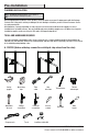
Pre-Installation (continued) B. IPS Measuring tape Tube cutter Key hole saw Adjustable wrench Phillips screwdriver Flathead screwdriver Silicone sealant Thermometer Thread sealant tape Flashlight Strap wrench Pipe wrench SI LI C ON E Safety goggles C.
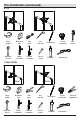
Pre-Installation (continued) D. CPVC+COPPER COPPER COPPER Measuring tape Tube cutter Key hole saw Thermometer Thread sealant tape Flashlight LI CO NE Safety goggles SI P i pe J o in t C o m p ou n d Adjustable wrench Phillips screwdriver Flathead screwdriver Silicone sealant 5 Strap wrench CPVC cement P i pe J o in t C o m p ou n d CPVC cleaner HOMEDEPOT.COM/GLACIERBAY Please contact 1-855-HD-GLACIER for further assistance.
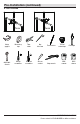
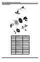
Pre-Installation (continued) PACKAGE CONTENTS A B C D E F J G K I L H Part Description Quantity A Shower flange 1 B Shower arm 1 C Shower head 1 D Valve body 1 E Installation plate 1 F Escutcheon 1 G Handle assembly 1 H Screw 2 I Plaster guard 1 J Plug 1 K Tub spout 1 L 2.
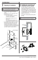
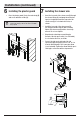
Installation 1 Preparing for installation the valve body and 2 Installing removing the plaster guard □ The plaster guard (I) is positioned so that it is flush with the finished wall. This ensures that the valve will be at the correct position to accept the trim. The depth for the valve body (D) in wall is measured from the center of the shower outlet to the finished wall surface. The accepted depth distance is 2-1/2 in. to 3 in..
Installation (continued) the supply 3a Installing connections the supply 3b Installing connections (for soldering) NOTE: The hot water supply lines go into the "H" inlet, and the cold water supply lines go into the "C" inlet. Do not use PEX or CPVC between the valve body (D) and tub spout (K). NOTE: The hot water supply lines go into the "H" inlet, and the cold water supply lines go into the "C" inlet. Do not use PEX or CPVC between the valve body (D) and tub spout (K).
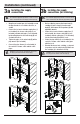
Installation (continued) 4 Back to back installation the water outlets 5 Flushing and checking for leaks □ NOTE: If you are not making a reverse or back to back installation, skip this step and continue with the step 5. □ If the hot and cold inlets are reversed (hot on right and cold on left), remove bonnet nut (1) from the valve body (D) with reversed supply connections. Rotate the cartridge (2) 180°, so H appears on the right.
Installation (continued) 6 Installing the plaster guard 7 Installing the shower arm □ Place the plaster guard (I) onto the valve body (D) and secure with the screws (H). NOTE: Be sure to position the plaster guard (I) correctly onto the valve body (D), with the side marked "SHOWER" facing upward. H □ Insert the long end of the shower arm (B) through the shower flange (A), and wrap thread sealant tape (not included) around the long end of the shower arm (B) in a clockwise direction, as shown.
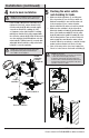
Installation (continued) 8 Installing the tub spout □ 9 Removing the plastic cap □ Place the spout (K) onto quick connection until the spout (K) becomes flush with the finished wall and tighten the screw (1) with with the Hex wrench (Hex: 2.5mm, L) provided. Before installing the escutcheon (F), remove the plastic cap (1) from the valve body (D) by twisting the cap in a clockwise direction.
Installation (continued) 10 Adjusting the temperature Adjusting the desired maximum B water temperature □ For colder water, adjust the red limit stop ring (1) in a clockwise direction and reinstall the red limit stop ring (1) onto the cartridge assembly (2). □ For hotter water, adjust the red limit stop ring (1) in a counterclockwise direction and reinstall the red limit stop ring (1) onto the cartridge assembly (2).
Installation (continued) the escutcheon 11 Installing and handle assembly □ Place the installation plate (E) and escutcheon (F) onto the valve body (D). Attach the handle assembly (G) by threading the base of the handle assembly (G) onto the valve body (D) and twisting clockwise until secure. Do not overtighten the handle assembly (G) as this could damage F the escutcheon (F). D E Down G 12 Checking for leaks □ Turn the handle (G) to the full on mixed position.
Installation (continued) 13 Installing the shower head □ Attach the shower head (C) to the shower arm (B). Hand-tighten only. B C NOTE: Do not use the thread sealant tape and do not use wrench to tighten shower head. If the screen filter (1) in the spray head (C) is blocked, turn off the water supply at angle valve and unscrew the spray head (C) from spray arm (B). Clean the screen filter (1) in the spray head (C) under running water with brush (2, not included).
Troubleshooting (continued) NOTE: Refer to the Service Parts section in this manual for a detailed drawing showing the location of the parts listed below. Problem Possible Cause Solution The cartridge is not properly installed. □ Reinstall the cartridge. The sealed washer on the cartridge is not in place. □ Check to ensure the sealed washer on the cartridge is in place or replace the cartridge. The bonnet nut is not tightened sufficiently. □ Use wrench to retighten the bonnet nut sufficiently.
Service Parts 1 2 3 4 5 7 6 9 Faucet ID tags can be found by removing the handle 8 10 Part Number Part Description Part Number 1 Shower flange RP80784* 6 Bonnet nut RP7072601 2 Shower arm RP38139* 7 Escutcheon RP80785* 3 Shower head RP38515* 8 Handle assembly RP13800* 4 O-ring RP60130 9 Plug RP70770 5 Cartridge RP20124 10 Spout RP33123* Part Description *Specify Finish Many replacement cartridges, aerators, and drain assemblies can be purchased at your local The H
Questions, problems, missing parts? Before returning to the store, call Glacier Bay Customer Service 8 a.m. - 7 p.m., EST, Monday - Friday 9 a.m. - 6 p.m., EST, Saturday 1-855-HD-GLACIER (1-855-434-5224) HOMEDEPOT.COM/GLACIERBAY Retain this manual for future use.
Modelo núm. HD873X-5D4405 HD873X-5D01 HD873X-5D04 HD873X-5D10H HD873X-5D35 SKU núm. 1005877850 315055926 315055920 315055925 317147249 GUÍA DE USO Y MANTENIMIENTO DORIND MEZCLADORA PARA REGADERA Y TINA, DE UN SOLO MANERAL Y UN MODO DE ROCIADO ¿Problemas, preguntas o piezas faltantes? Antes de regresar a la tienda, llama al servicio al cliente de Glacier Bay de lunes a viernes entre 8 a.m. y 7 p.m. y los sábados entre 9 a.m. y 6 p.m.(hora estándar del Este) 1-855-HD-GLACIER (1-855-434-5224) HOMEDEPOT.
Tabla de contenido Información importante .........................19 Garantía...................................................19 Pre-instalación .......................................20 Planificación de la instalación .............20 Herramientas y herrajes necesarios ....20 Contenido del paquete .........................23 Instalación ..............................................24 Cuidado y limpieza ................................31 Solución de problemas ...........................
Pre-instalación PLANIFICACIÓN DE LA INSTALACIÓN INSTALACIÓN AVANZADA: Consulta a un plomero o profesional antes de instalar este producto. Antes de comenzar la instalación de este producto, asegúrate de que no falta ninguna pieza. Compara las piezas con la lista de Contenido del paquete. Si falta alguna pieza o está dañada, no intentes instalar el producto. Comunícate con el servicio al cliente para piezas de repuesto.
Pre-instalación (continuación) B. IPS Gafas de seguridad Cortador de tuberías Serrucho de punta Termómetro Cinta selladora para roscas Linterna Llave de correa Llave para tubería SI LI C ON E Cinta métrica Llave ajustable Destornillador Destornillador de Phillips cabeza plana Sellador de silicona C.
Pre-instalación (continuación) D. CPVC+COBRE COBRE Cinta métrica Cortador de tuberías Serrucho de punta Termómetro Cinta selladora para roscas Linterna SI LI CO NE Gafas de seguridad COBRE Llave ajustable Destornillador Destornillador de Phillips cabeza plana P i pe J o in t C o m p ou n d Sellador de silicona 22 Llave de correa Cemento CPVC P i pe J o in t C o m p ou n d Limpiador CPVC HOMEDEPOT.COM/GLACIERBAY Para obtener asistencia, llama al 1-855-HD-GLACIER.
Pre-instalación (continuación) CONTENIDO DEL PAQUETE A B C D E F J G K I L H Pieza Descripción Cantidad A Brida de la ducha 1 B Brazo de la ducha 1 C Cabezal de la ducha 1 D Cuerpo de la válvula 1 E Placa de instalación 1 F Placa protectora 1 G Ensamblaje de la llave 1 H Tornillo 2 I Protector de yeso 1 J Tapón 1 K Caño de la bañera 1 L Llave hexagonal de 2.
Instalación 1 2 Cómo prepararse para la instalación PRECAUCIÓN: Cierra siempre el suministro de agua antes de retirar un grifo existente o reemplazar alguna parte del mismo. Abre la llave del grifo para liberar la presión de agua y asegúrate de que el suministro de agua esté completamente cerrado. □ □ □ El protector de yeso (I) se coloca de forma tal que esté al ras con la pared acabada. Esto garantiza que la válvula estará en la posición correcta para aceptar el regulador.
Instalación (continuación) instalar las conexiones instalar las conexiones 3a Cómo 3b Cómo de suministro de suministro (para soldar) NOTA: Las líneas de suministro de agua caliente van en la entrada “H” y las de agua fría, en la entrada “C”. No uses PEX ni CPVC entre el cuerpo de la válvula (D) y el caño de la bañera (K). NOTA: Las líneas de suministro de agua caliente van en la entrada “H” y las de agua fría, en la entrada “C”.
Instalación (continuación) de parte posterior purgar las salidas de agua 5 Cómo 4 Instalación con posterior y chequear que no haya fugas □ NOTA: Si no estás realizando una instalación inversa o de posterior con posterior, salta este paso y continúa con el paso 5. □ Si las entradas de agua caliente y fría se revierten (caliente a la derecha y fría a la izquierda), quita el bonete (1) del cuerpo de la válvula (D) con conexiones de suministro revertidas.
Instalación (continuación) 6 Cómo instalar el protector de yeso instalar el brazo de la 7 Cómo ducha □ Coloca el protector de yeso (I) en el cuerpo de la válvula (D) y asegúralo con los tornillos (H). NOTA: Asegúrate de colocar el protector de yeso (I) correctamente sobre el cuerpo de la válvula (D), con el lado de la marca “SHOWER” (ducha) hacia arriba.
Instalación (continuación) instalar el caño de la 8 Cómo 9 Cómo quitar la tapa de plástico bañera □ □ Enrosca el caño (K) en la conexión rápida hasta que el caño (K) quede a ras de la pared con acabado y aprieta el tornillo (1) con la llave hexagonal (hexagonal de 2.5 mm, L) incluida. Antes de instalar el escudete (F), quita la tapa plástica (1) del cuerpo de la válvula (D) girando la tapa en el sentido de las manecillas del reloj.
Instalación (continuación) 10 Cómo ajustar la temperatura Cómo ajustar la deseada B temperatura máxima del agua □ Para agua más fría, ajusta el aro de retención del límite rojo (1) hacia la derecha y vuelve a instalarlo (1) en el conjunto del cartucho (2). □ Para agua más caliente, ajusta el aro de retención del límite rojo (1) hacia la izquierda y vuelve a instalarlo (1) en el conjunto del cartucho (2).
Instalación (continuación) instalar la placa protectora 11 Cómo y la ensamblaje de la llave □ Coloca la placa de instalación (E) y la placa protectora (F) en el cuerpo de la válvula (D). Coloca el conjunto de llave (G) enroscando la base del conjunto (G) en el cuerpo de la válvula (D) y girando hacia la derecha hasta que quede seguro. No apretar demasiado el conjunto de llave (G) ya que esto pudiera dañar la placa protectora (F).
Instalación (continuación) instalar el cabezal de 13 Cómo la ducha □ Fija el cabezal de la ducha (C) en el brazo de la ducha (B). Ajusta sólo con la mano. B C NOTA: No uses la cinta selladora para rosca y no uses la llave para apretar el cabezal de la ducha. Si el filtro de malla (1) del cabezal del rociador (C) está bloqueado, cierra el suministro de agua en la válvula angular y desenrosca el cabezal del rociador (C) del brazo rociador (B).
Solución de problemas (continuación) NOTA: Consulta en la sección de piezas de repuesto de este manual una ilustración detallada sobre la ubicación de las piezas enumeradas más abajo. Problema Posible causa Hay una fuga o filtración desde el caño cuando la manija está cerrada. □ □ □ Solución El cartucho no está instalado correctamente. La arandela de sellado del cartucho no está en su lugar. La tuerca ciega no está lo suficientemente ajustada.
Piezas de repuesto 1 2 3 4 5 7 6 9 Las etiquetas de identificación del grifo pueden encontrarse al retirar la llave.
¿Problemas, preguntas o piezas faltantes? Antes de regresar a la tienda, llama al servicio al cliente de Glacier Bay de lunes a viernes entre 8 a.m. y 7 p.m. y los sábados entre 9 a.m. y 6 p.m.(hora estándar del Este) 1-855-HD-GLACIER (1-855-434-5224) HOMEDEPOT.COM/GLACIERBAY Conserva este manual para uso futuro.