
Installation

4
WARNING -- IMPORTANT SAFETY INSTRUCTIONS
To reduce the risk of electric shock, burns injury or fire follow these precautions:
1. Install and use this cabinet in a household or commercial residential setting.
2. Do not alter or add any features or other appliance not recommended by the manufacturer.
3. Do not alter the factory installed Electric Option shelf or any of its features or appurtenances.
4. This unit’s service wiring and electrical connections must be made by a Licensed Electrician in
a manner that conforms to the National Electric Code.
5. This unit requires a Class A 120V AC 20 Amp GFCI circuit breaker (Ground Fault Circuit Inter-
rupter) when used in bathrooms and all other locations required by the National Electric Code.
GROUNDING: This product must be connected to a grounded, metal permanent wiring system or an
equipment-grounding conductor must be run with the circuit conductors and connected to the equipment
terminal or lead on this product.
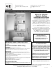
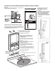
Mirrored Cabinet Electric Option
Unpack all parts carefully and protect Glass and Mirror parts during installation.
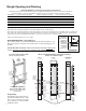
STEPS FOR WIRING ELECTRIC OPTION:
See illustrated steps on page 5.
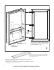
• Electrician should have roughed electrical wire for
selected access hole in cabinet (See page 6).
- For Recessed -- Left or Right side access
(as determined at the time of order by the door hand).
- For Surface Mount - rear access (See page 9).
NOTE: Only remove the Electric Option shelf’s front
cover to make the electrical connection.
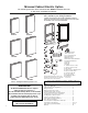
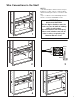
1. Remove three screws from the bottom of the Electric
Option shelf using the Allen wrench supplied. Gently lift
and rotate Electric Option shelf’s front cover forward for
access to the electrical connections.Take special care
not to scratch the inside of the cabinet when lower-
ing the electric shelf front cover for wire access. Let
cover hang from the switch wire to make the electri-
cal connection within the shelf.
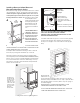
2. Feed electric wire through access hole’s plastic bush-
ing with at minimum of 20” excess wire. Install cabinet.
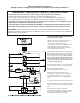
3. Connect Black, White and Green to
matching wiring within the junction connector.
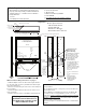
4. Replace the Electric Option shelf front cover
making sure not to crimp or pinch the switch wires and
other electrical connections. Do not use any other
screws other than the Allen screws supplied with the
cover.
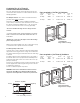
5. Insert white opal acrylic shelf on Electric Option shelf.
6. Install door. Plug Defogger tether into the nearest de-
fogger outlet located on the bottom of the Electric Option
shelf.
7. Check with power supply on-- illuminated
indicator switches: Right Side -- Heated Door Defogger
(blue); Left Side --Integral LED Light (white). Turn off
power supply until final finishes are complete.